The LK&O model railroad is an HO scale proto-free lance model railroad representing a small section of Lapeer MI, a bend in the Potomac river at Kitzmiller MD, and a swath of property in Akron OH. These three areas have specific relevance to me and railroading. In real world geography, the three areas are separated by hundreds of miles and have no real relationship to each other, railroad or otherwise. However, on my model railroad these are the three locales and the interconnecting rail lines that collectively are known as the LK&O Railroad.
The name “LK&O Railroad” is really nothing more than a convenient way of referring to my hobby. A quick check of registered reporting marks confirms the LK&O is not a real railroad. Let’s face it… An adult man simply can’t use the term “toy trains” while retaining any dignity at all and if you say “model railroad” then people tend to stereotype you as either nerdy or grandpa. LK&O, on the other hand, causes people to ask “What’s an LK&O?” Well, let me tell ya’…
The components of the LK&O are:
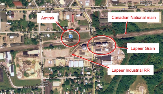
Lapeer MI – The Canadian National Flint subdivision runs through Lapeer. There is an active Amtrak station, Lapeer Grain, and the Lapeer Industrial RR (1.34 miles of track) serving small local industries. Fortunately, all three of these are located in very close proximity to each other and as such are extremely well suited for modeling. Although the tracks are located on the opposite side of town from where we live it is still our neighborhood. Plus, it is close by for observing details so is the most prototypical modeled section of the layout. With the grain mill and assorted businesses served by the Lapeer Industrial RR there are ample opportunities for interesting car switching to a varied selection of industries.
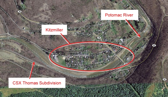
Kitzmiller MD – CSX hauls coal from the West Virginia and Maryland mines on the Thomas subdivision which follows the Potomac river along the WV and MD border. At a very graceful and picturesque horseshoe bend in the river sits Kitzmiller. This area is scene #2 on the LK&O. While the real life mines are not all that close to Kitzmiller, selective compression allows me to put the Mettiki Coal loading facility in the same relative area on the layout. Coal loading and the transport of loaded and empty hopper cars is the activity here. Kitzmiller is quaint little town nestled along the river bank and framed by steep mountains on both sides. A visual delight!
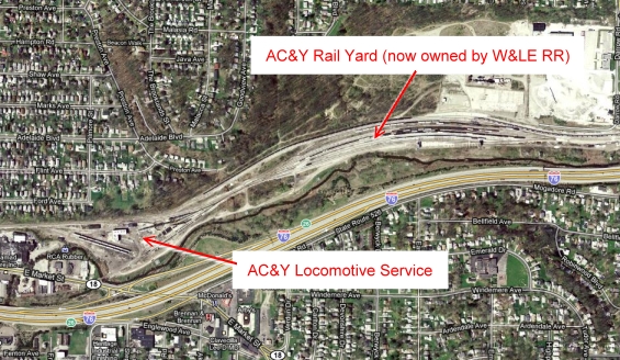
Akron OH – Specifically, Brittain Yard. This is scene #3, the primary scene on the LK&O, and is the focal point as well as occupying the most basement real estate. Brittain Yard was AC&Y’s primary classification yard. From there the rubber industries of Akron were served as well as manyl other businesses along the right-of-way. Additionally, the Akron Barberton Belt RR interchanged with the AC&Y at the yard limits. The east and west bound mains eventually interchange with CN and CSX respectively. Brittain Yard is the area of constant action on the LK&O.
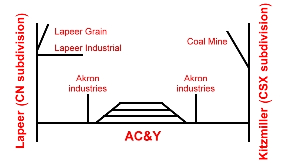
An operational schematic of the LK&O. This is functionally how the railroad works but, of course, not how it is physically arranged on the layout.
The challenge is successfully and believably integrating the three scenes into a 25 feet by 25 feet space while preserving the illusion of distinctly different locations linked by rail. All the while trying to get the longest possible mainline length so the trains cover some distance before arriving at their destinations. On the track plan tab is my attempt to solve this challenge.


WOW, another person interested in the AC&Y ! ! ! Go figure ! I’m an Akronite who grew up in the shadow of the Goodyear air dock. I*’ve watched actual commercial passenger planes takeoff from the munisipal airport in Ellet. I also remember the B&O steam switcher hauling boxcars to and from Goodyear Aircraft (thats what it was called before changed to (Aerospace)plants @ Kelly ave. & Waterloo rd. I’m glad to hear the Intermoutain is making some AC&Y equipt. I had to fight off another bidder for my 1 little N-scale boxcar ! I don’t always get on here, so I glad I caught your message !
George @Oh.Vet’s Home,Sandusky
George, we must have grown up in the same neighborhood. I lived within a block of Akron muni. The Goodyear air dock could be seen from our living room window! Stay tuned. Construction of the railroad is about to begin. Perhaps you will recognize places on it once it starts to take shape.
I too am building a double deck layout and went through the lighting issues at great length. I settled on lighting similar to Joe Fugate using lamp holders at 2′ centres with energy saving Halogens @ 28watt and 42watt bulbs. These run quite cool and give excellent natural warm light. I have 7 circuits of 22 lamps per circuit for daylight and 22 also for night lights (blue). I am intending to convert to LED lamps once Osram release dimmable LED lamps of 3-7 watt, sometime in the future.
My lighting will be controlled with the Light-Lynx Day/night system and their fast time clock. I can send you some photos to show you the current lighting result if you would like.
Phillip, what size circuit breaker(s) are you using? I have available only a single 15A circuit without pulling more wire from the panel.
Hi Alan, I live near You, grew up in Atlas it was good of you to comment on my posting about using cork on foam. I send my bench work to a company in Indiana to lay track, install the turntable and wire the DCC turnouts. that was a year ago Sept. I am at a stand still waiting for its return. I started a shelf extension just to keep me interested in the hobby. I am always like talking and see others layouts. maybe we can get together, I’d like to see your progress.
Tom
Tom,
Wow, a year is a long time to wait. Hope they return it to you soon. My progress is pretty much just what you see here on the blog. I wish I were further along or had more to show you. At least I am making steady progress. I may take you up on the visit offer once I have something worth viewing. Perhaps you can join me when my first train rolls under its own power. That will be a very special day indeed.
Alan, Howard assured me he would have it finished by February Track laid,turnouts wired now building control panel and testing. He’s send me videos of the BigBoy running around the two main lines. If I get it back and setup in the basement first , I will have you and a few friend over.
Keep in touch by E-mail
Tom
Alan,
Found your blog recently and have been following progress. Particularly like the shots of risers development and the use of the anvil! Great stuff.
I too like Kitzmiller, MD and almost used that location on my ClinchValleyLines. But settled, happily, on the SW area of Virginia.
Recently I acquired a AC&Y OB 40 foot boxcar (Accurail) HO scale that is interesting to me—I like OB cars— but has far less value to me than it would to you. Be glad to send it to you—-if you want it. Like most Accurail it has some compromises but if you want it, let me know. Gratis. Currently in Europe, this will have to wait until we return mid Oct.
Roger Sekera
Potomac, MD
Roger, that is a very generous offer.
Alan,
In mid Sept—when I was still in France—we talked about trading, sending you an Accurail 40′ OB boxcar AC&Y (#1177)for one car from your roster. If that still makes sense to you, any of the Athearn C&O hoppers would be fine.
Roger Sekera
Potomac, MD
Alan,
Just read your post on MRH relative to nickel plating athearn wheels and then your link on setting up a nickel plating process to DIY. I am now 70 years young and have accumulated about a thousand feet of old brass rail, much of it removed from the old fiber tie stock that fell out of favor when plastic ties entered the market and finally when “nickle-silver” rail became the standard. My thought process has always been to use the old brass rail to hand-lay my track after I found a way to nickel plate the wheel contact areas of the rails, or to battery power my now DCC and sound locomotives by building-in automatic, in locomotive, re-chargers and providing recharging powered sections of track in appropriate “refueling” areas of the layout.
In your opinion, is nickel plating the rail tops a feasible project” I recognize that some serious experimenting will be required to accommodate the somewhat unique shape of the rail heads.
John R.
John, I have no practical experience with plating so I can’t offer much guidance. Uniformity of the plating is going to be critical. Might have to try a piece and see what results you get. If you live in a major city you might consider contacting a plating shop to see what they would charge to do the whole batch. Their process would be much more refined and produce a better result I would think. The materials mentioned in the article are low cost and readily available so doing a test piece should be relatively easy. Let us know how it comes out.
Old AC&Y right of way, west of Akron, practically goes through my backyard in Medina. Nice modeling and professional looking website. Kudos!
Hi Alan, I neglected to answer your reply to my lighting system way back, that I am using similar to yours. I was using 28 watt and 42 watt energy saving halogen globes running through 10 amp circuit breakers. I have now converted to 5 watt dimmable led corn bulbs that give off tremendous brighter light, no heat and will use little power all for $3.50 each here in Australia. Congratulations on your milestone with module 13.
I’m interested in how you designed lapeer Michigan. The lapeer industrial railway seems like a manageable size to build into a model railroad. Do you have any track plan developed for this part of the railroad you carever to share with me? I’m interested in building this prototype but admittedly am not very good at designing things. Thanks
Andrew, I can supply an XTrkCAD file if that helps you. My rendition of Lapeer Industrial Railroad has some artist’s liberties but it is close.
Hello Alan,
This is a great site you have here and some really impressive work you are doing. Thanks for sharing. Your expedition into lighting the lower deck will be of help to me as I will soon be adding the upper deck to my basement layout. I noted in your blog that you said the LED strips didn’t put out enough light and that you needed the CFL bulbs to do the heavy lifting. I don’t yet know how many (total) lumens per foot I should be shooting for, but am trying to figure that out. Can you tell me how many lumens per foot you are getting out of your LED strips and how many lumens are produced by each of your CFL bulbs?
Jamie,
The LED strips I used are spec’d at 500 lumens / meter.
The CFLs are 550 lumens each. The CFLs are mounted on 2 foot centers so I am going to guess roughly 1000 lumens / meter.
There are a bunch of posts about my lighting starting here:
https://lkorailroad.com/lighting-proof-of-concept/
Alan: Thanks for such a great site. I’ve been following your build and have been intrigued on way numerous occasions regarding your diligence and steadfastness to do the job right. Thanks for the SSL explanation and for taking it on the monetary chin as it were so we could all enjoy your work.
My pleasure Jeff.
Hi Alan,
great side!!
I can`t find the final schematic of the district circuit breaker. Would You be so kind to tell me where to find, or send it to me.
Juergen,
You are right! My mistake. I did not provide a schematic on the original post. Sorry about that. Fixed now. The circuit breaker schematic is available at: https://lkorailroad.com/circuit-breaker-and-block-detector-final-units/
Hi Alan,
I am interested in the RailPro system and was wondering if I could visit your layout sometime soon to see it up close and personal? I live pretty close to you.
Thanks
Richard
Richard,
You are welcome to visit anytime however the layout is nonfunctional at this time. I am in the process of mounting and wiring the control panels. There are hundreds of dangling bare wires at the moment. Damaging shorts will occur if I apply power before all of the control panels are in place. I have no way to demonstrate RailPro for you right now. If you can wait we can run RailPro all you want after the control panels are finished.
You may want to take a look at the Users Group at http://rpug.pdc.ca
Do you have a youtube channel so i can check your progress. It’s amazing how little switching there is in Lapeer now compared to when i was growing up there in the 70’s gtw used to have a switch job that came every day to switch industries in Lapeer also the penn central would make an appearance 3 or 4 times a week
I have a YT channel however there are only a few LKO videos on it. I don’t make progress videos. Progress is detailed in the regular blog posts.
https://www.youtube.com/user/funinthebasement/videos
I would like parts details for your Tortoise circuit boards.
I am working on a layout and, like you, want to control my turnouts with push buttons. My plan is to put the push button next to the turnout. Conductors/brakemen-engineer teams are to follow their trains around the layout. Instead of a caboose type of throw they simply push the button when the turnout is clear they may proceed with their work.
I saw the integrated circuit from Digi-Key (PB1085-ND) that you used. What are the part numbers and sources for other components, if you will share them.
Thank you,
Kennedy
Kennedy,
I see from another comment you found the post for the Tortoise boards and was able to get part numbers.
I left a reply to your comment on that post with the part number for the connector.
https://lkorailroad.com/tortoise-printed-circuit-boards/
Good luck and have fun!
Kitz is only an hour or two West of where I live now, and only a few miles away from Keyser WV, the terminus and interchange point for my prototype, the Twin Mountain & Potomac RR, a three foot narrow gauge road that lasted only a few years between 1911 and 1920. I’m recreating many of the unique features, freelancing it into a longer lifespan and greater expansion and operation and just generally planning on having lots of fun with it. I’ve already overcome one big problem- motive power. The TM&P ten wheelers were very close to Tweetsie #12- I picked up two T&T Art Hobbies ET&WNC HOn3 brass ten wheelers to use.
Wayne, if I need a quick pic of something in Kitzmiller I know just who to call! 🙂
Alan
There are many of us who would love to hear how the LK&O is doing? Any progress to report?
Sorry George, very little progress to report. Lately life hasn’t afforded me time to work on the railroad. Soon!
Alan,
A question about the benchwork fasteners. It appears the connectors you used for the angled connections are the Simpson Strong-Tie LS Skewable Angle or something similar. The recommended fasteners for them are 1 1/2″ nails or screws. But I will be using 3/4″ thick material. What did you use? I cannot tell from your pictures.
Larry Derr
Larry,
You are correct. LS Skewable Angles were used. I fastened them with #6 x 1/2″ panhead sheet metal screws. More detail can be found here: https://lkorailroad.com/benchwork-construction-methodology/
Alan,
Do you have a general schematic of the electrical layout of your enterprise? I am getting ready to start an 11×16 project in my new house with a separate workroom of 11×6. I am trying to make sure that I have accommodated for all power requirements (lighting, dcc, etc.) prior to the drywall going up.
Nick,
I do not have a single consolidated schematic of the entire room and layout. There are wiring schematics strewn throughout the blog posts showing specific circuits but that would be a difficult way to collect all of the wiring information.
From a 110v and drywall perspective I can tell you it is quite simple. Wall plugs are spaced around the room just as any other room would have. They are all on a single 15A branch circuit. Aisle lighting is the house original ceiling box branch circuit.
Power for the layout lighting and the railroad itself comes from three dedicated 20A branch circuits pulled from the load center. None of the 20A circuits are behind drywall. They are run through floor joists above the drop ceiling. All standard house wiring practice.
These posts may be helpful:
https://lkorailroad.com/lighting-control/
https://lkorailroad.com/powering-the-lko-part-i/
https://lkorailroad.com/lighting-control-update/
https://lkorailroad.com/lighting-system-operational/
Alan, that does help.
In the last photo on “Powering the LK&O – Part I” Am I looking at the labels PS5, PS1, PS3, PS2, PS4 from left to right correctly?
Referencing this photo and “Lighting System Operational” I get:
PS5 “Accessory Buses” 29A 12V
PS1 “Zone 1 and 2 LEDs”? 30A 12V?
PS3 “Lower LEDs” 50A 12V?
PS2 “Zone 3&4 LEDs” 30A 12V?
PS4 Railroad = 7A 16v
If this is correct, I will go from there.
Another question about power. I assume you are using DCC, but I haven’t seen any posts by you about it (I May have missed them), but I am not sure that DC wouldn’t have similar requirements. I am using Digitrax and it is suggested to break up a layout into zones controlled by separate boosters each having a separate power supply. My intent is to complete my trackwork in 4 phases using 4 zones. Do you only have one P/S for the entire layout? Am I missing something here?
Nick,
Your read is correct about the power supplies in the photo. There are a lot of LED strips hence so many power supplies dedicated to them. Also, per the manufacturer, the power supplies must be de-rated somewhat when mounted vertically.
My railroad is RailPro, not DCC. The track is wired much like you would for conventional DC. The layout is broken down into zones that I call power districts. There are 15 power districts on the upper deck each fed by the single 7A power supply. Each district is protected with a circuit breaker. Circuit breaker trip currents are set according to the maximum expected load on the track segment served. The heavy wire gauge power bus allows the 7A power supply to be swapped out for a higher amperage unit if needed in the future.
To help visualize the arrangement, here is a map of the upper deck power districts showing the end points of each district and the location of circuit breakers.
https://lkorailroad.com/wp-content/uploads/2023/02/power_districts.jpg
Hope that helps.