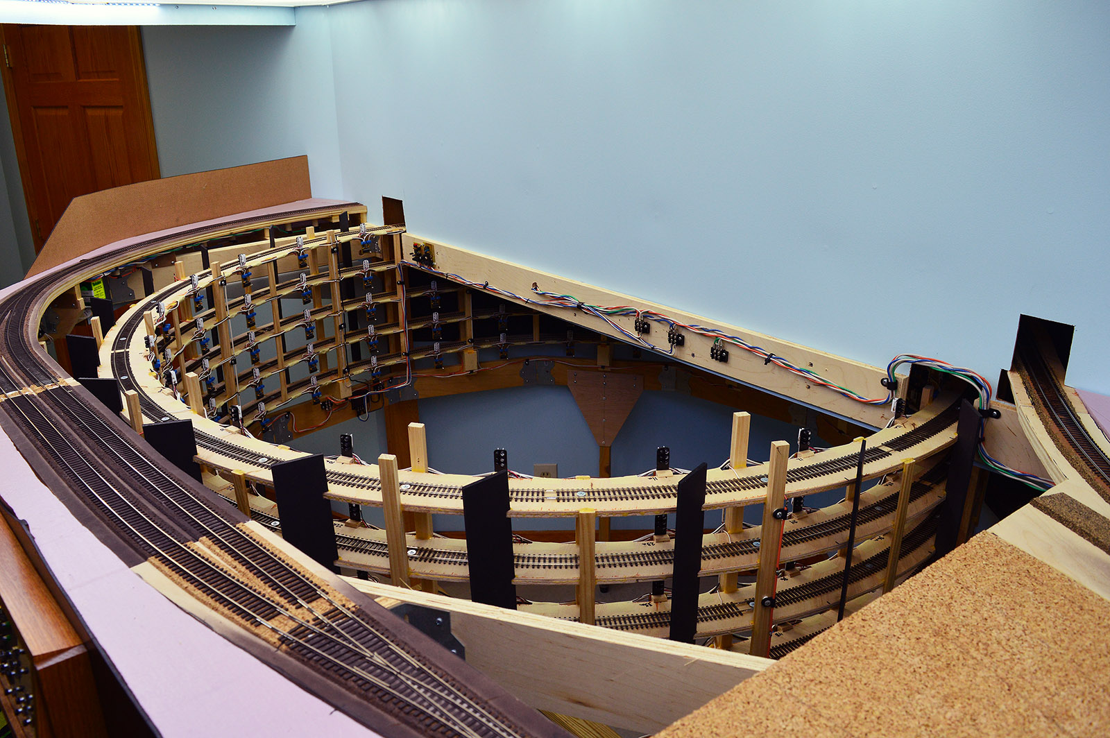
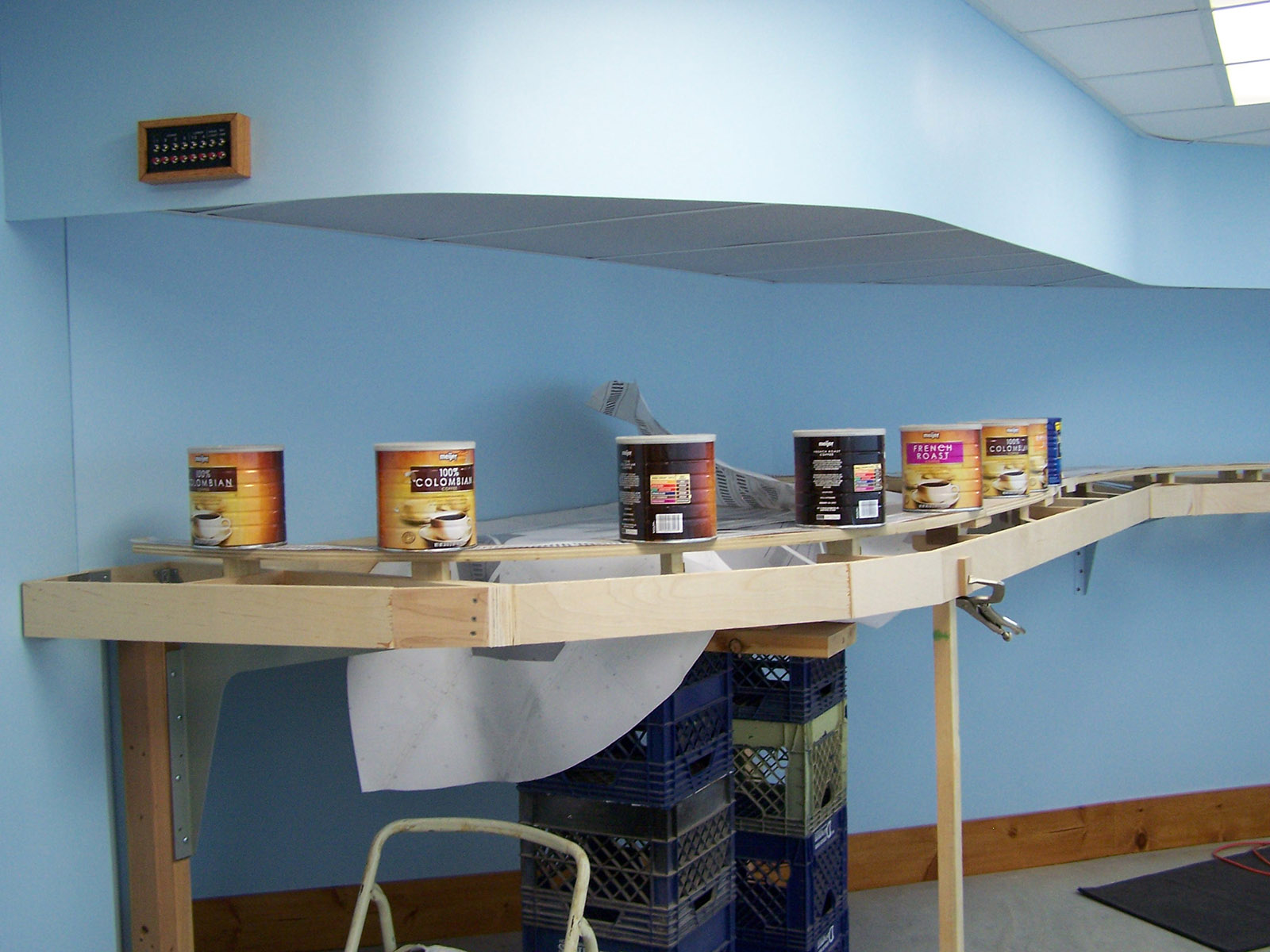
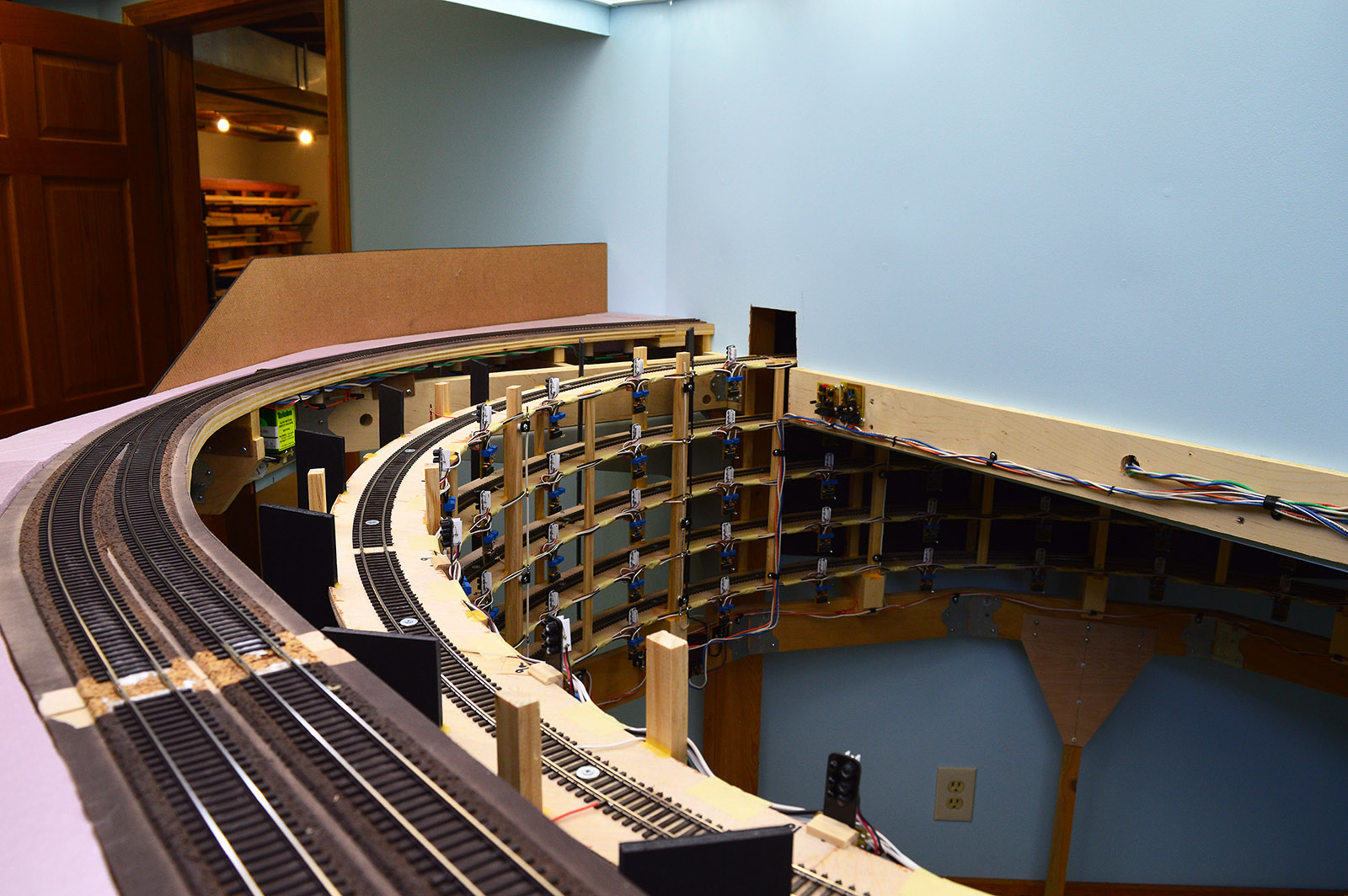
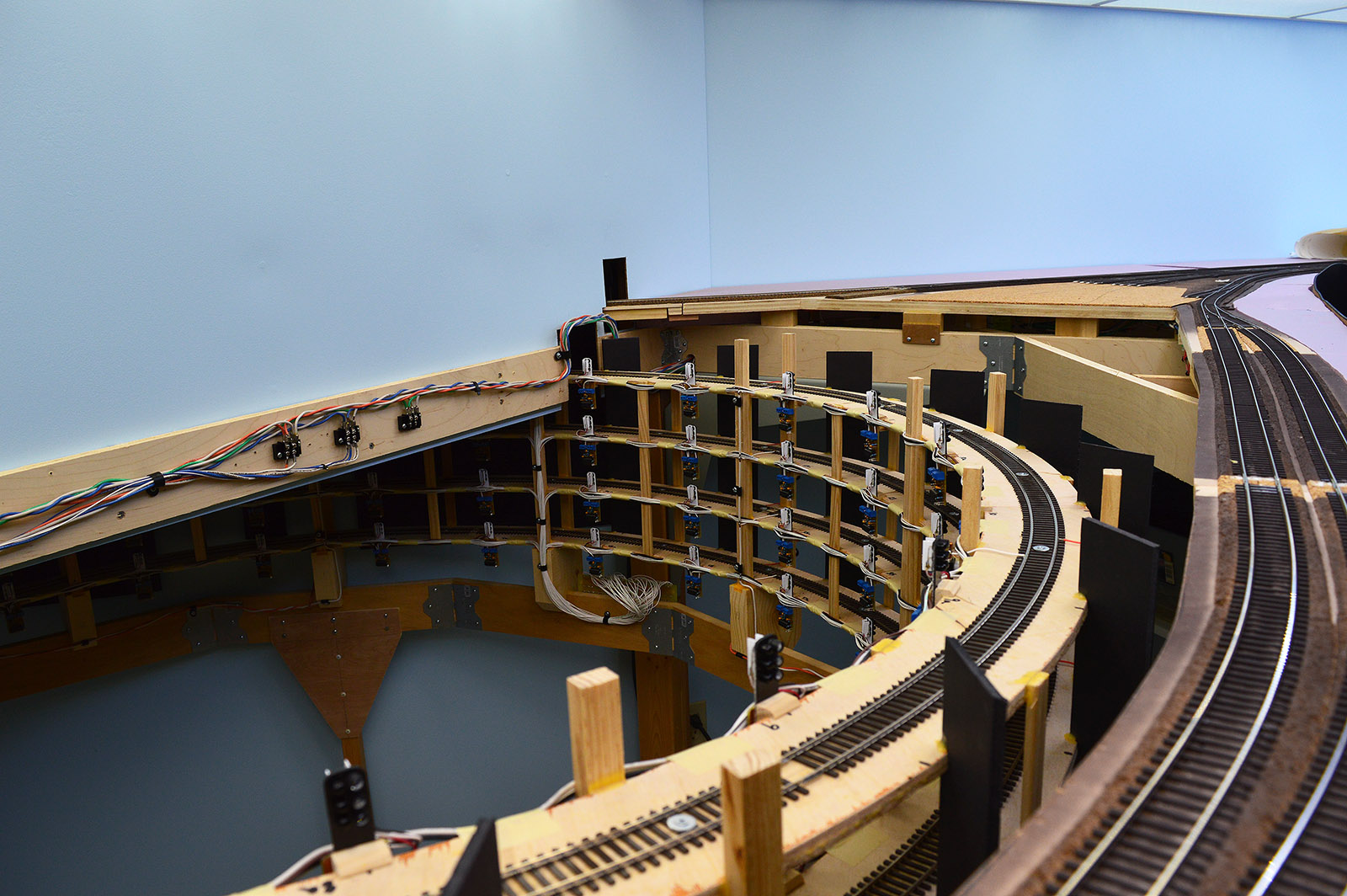
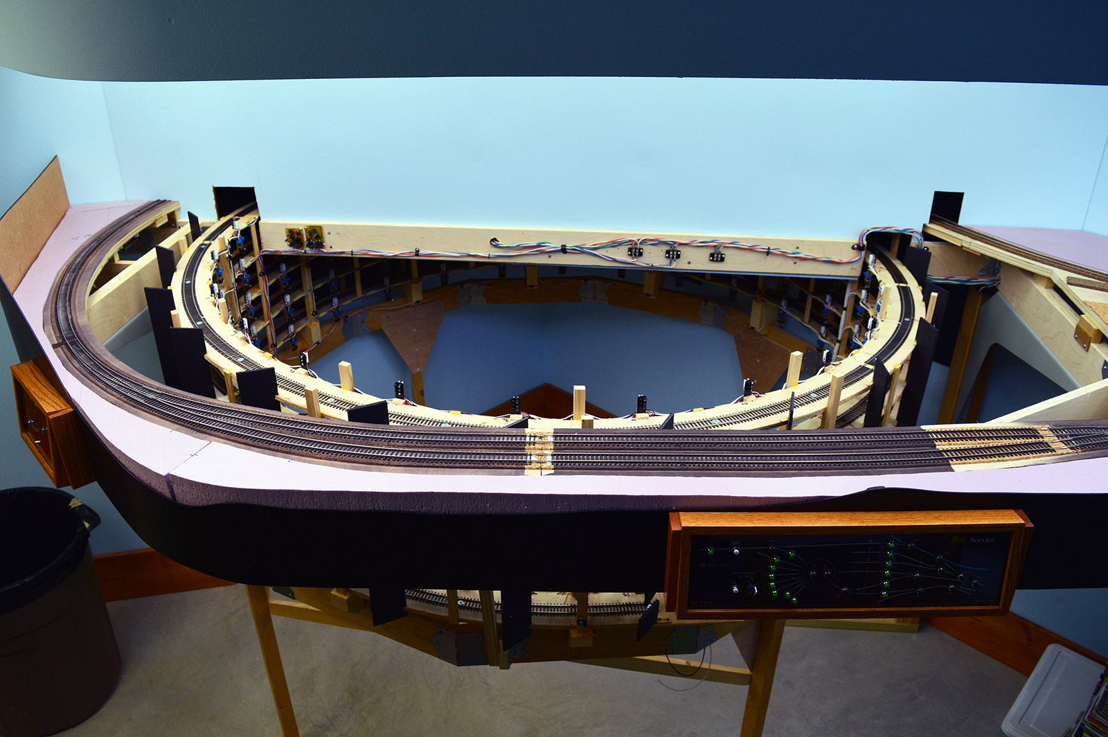
The south helix has been installed into the layout. Much to my relief it fit pretty good. My one oops was the buss wiring routing along the backdrop wall. Fortunately, a little rerouting on the backside of the wall freed up enough slack to arch the wires over the helix. With that one exception I am real happy with the fit.
The Big Lift
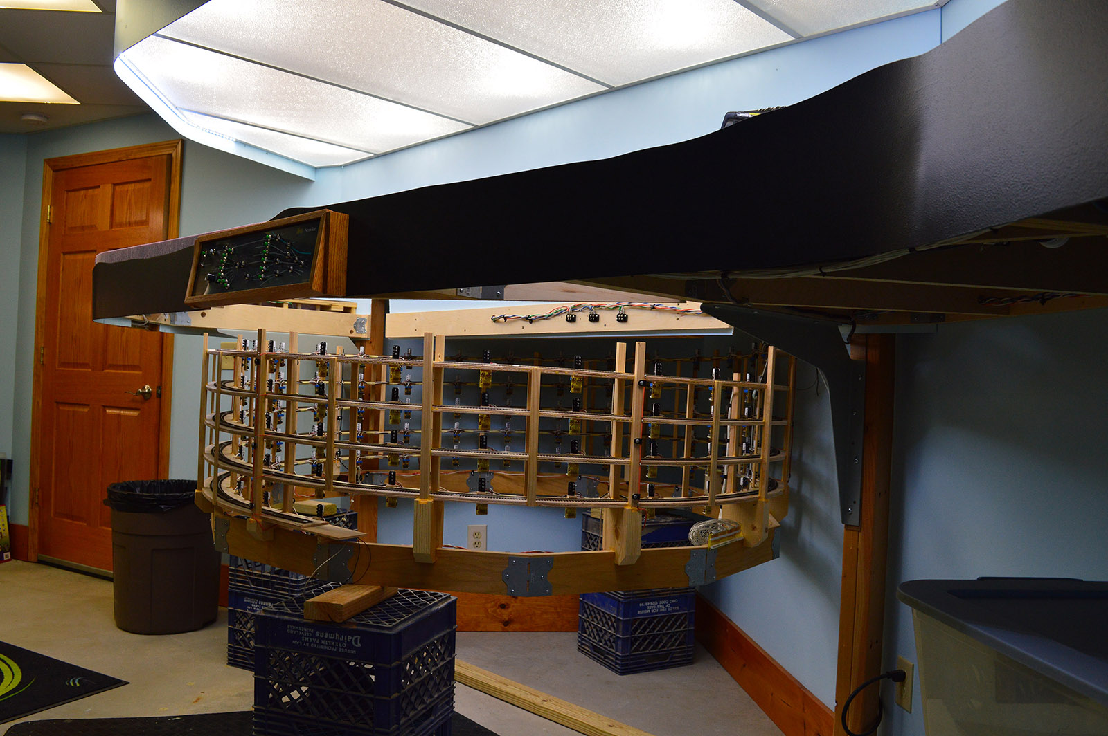
Moving the helix from the shop to the train room didn’t require a D9 Cat after all. In fact, the helix is surprisingly light given its bulk. Easily managed by two people.
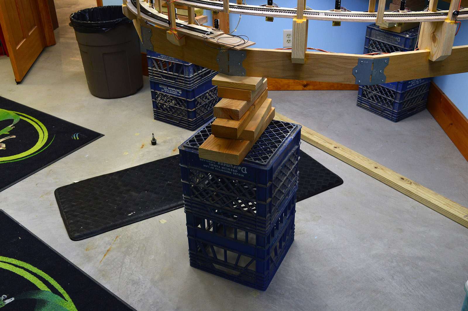
We laid the helix on its side on a rug and then slid it through the train room door. Once inside we returned it to the upright position before carefully sliding it under the layout. With a person under the layout on each side of the helix we began the lift. Got the helix up onto a single milk crate and then up onto a second crate. From there on up the helix was raised 1-1/2″ at a time with lumber cribbing. The final step was to rotate the helix to position the entry and exit ramps in the right place. The lift didn’t require any of the back breaking effort I expected it to. It was quite easy, in fact.
Room to Work
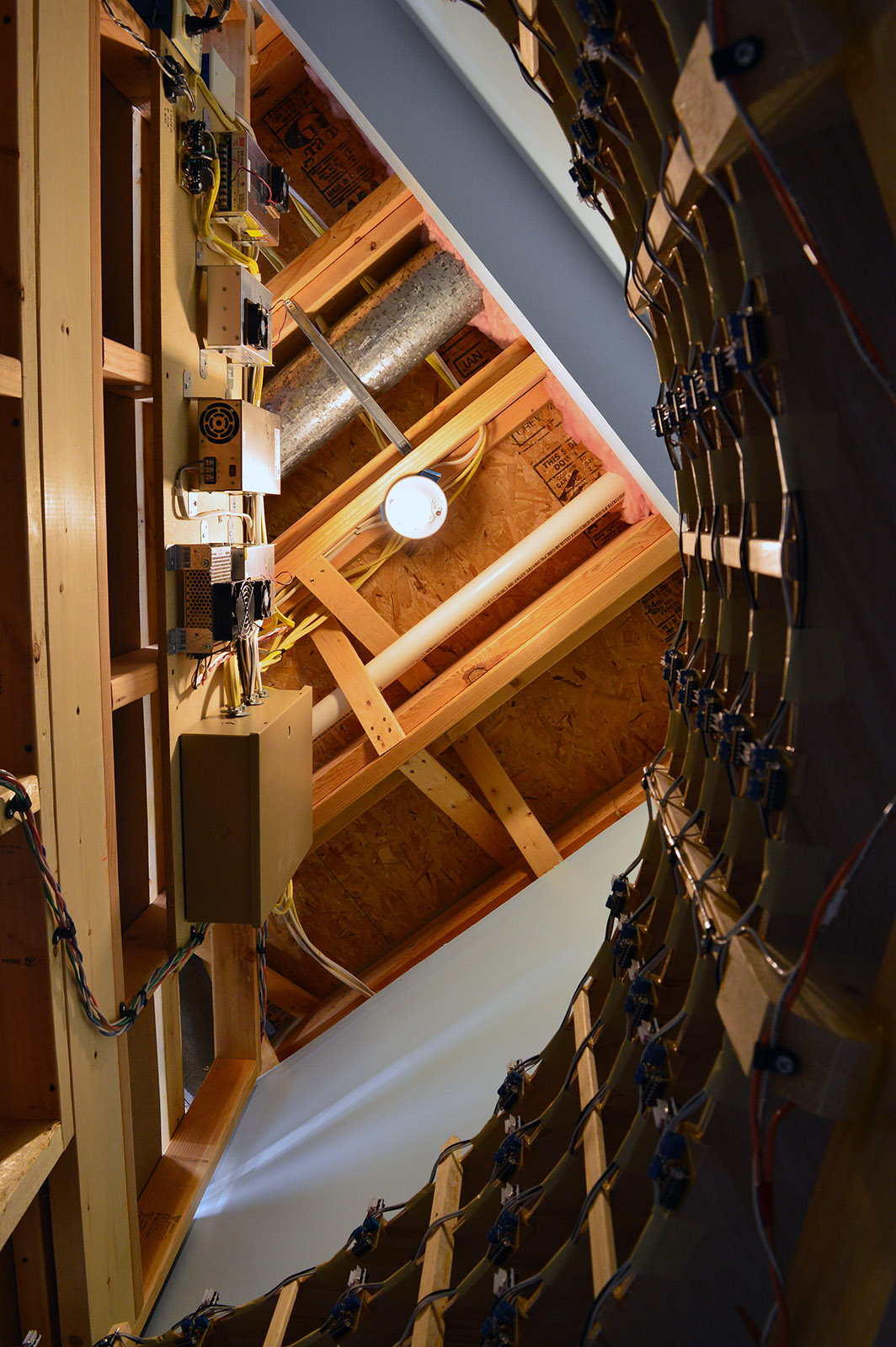
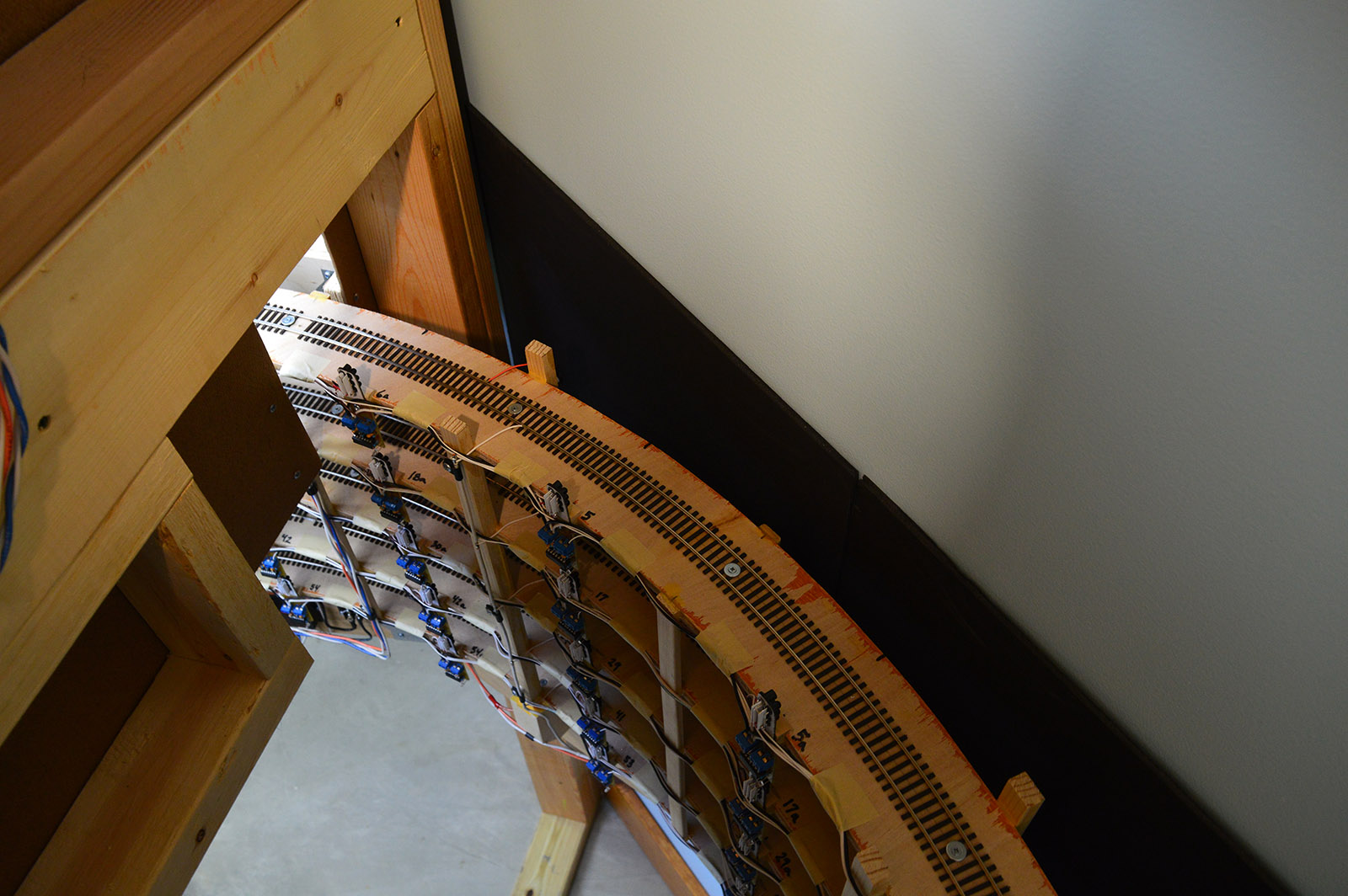
One of my big concerns during the design phase was would there be enough room to stand and work inside the helix behind the backdrop wall. That is important because the layout and lighting power supplies are mounted on the back of the wall. You can make all the drawings you wish, measure six ways to Sunday and still not be sure there is adequate room for a human to shimmy under and stand up within the confines of a half circle sitting in a triangle. One of the first things I did with the helix in place was to make sure I fit.
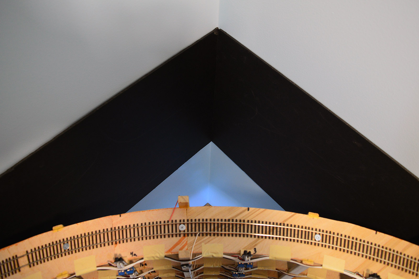
No problem! Relieved to know there is plenty of space. A view from the floor looking straight up:
A Leg to Stand On
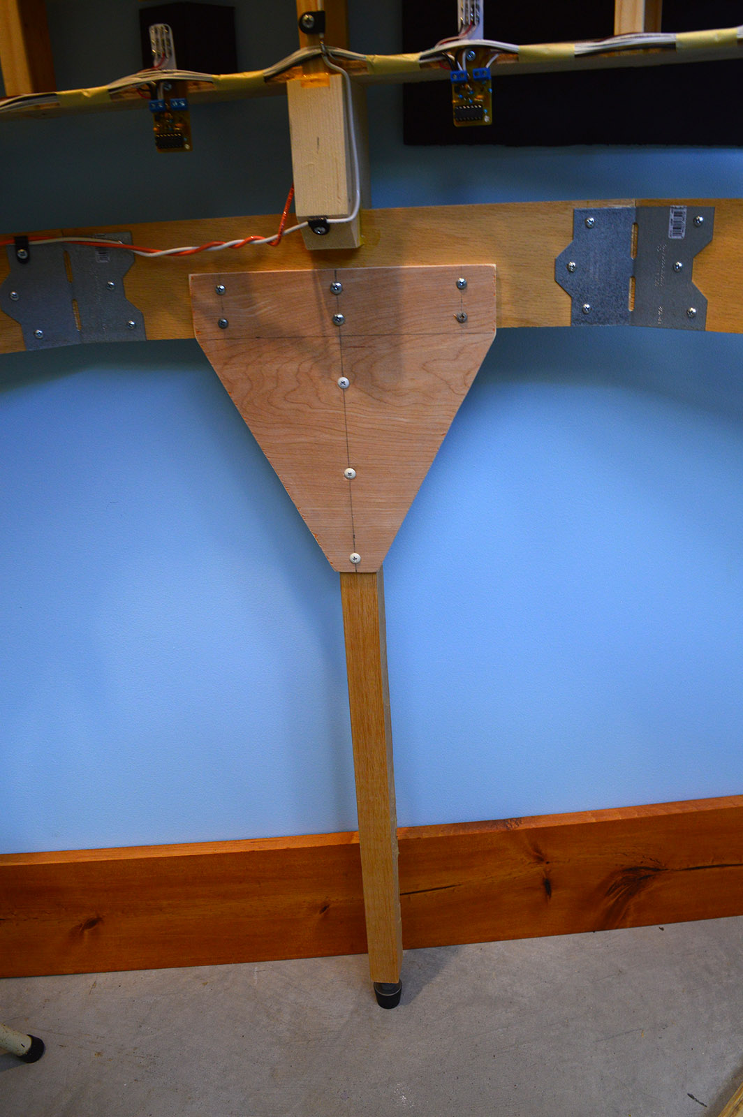
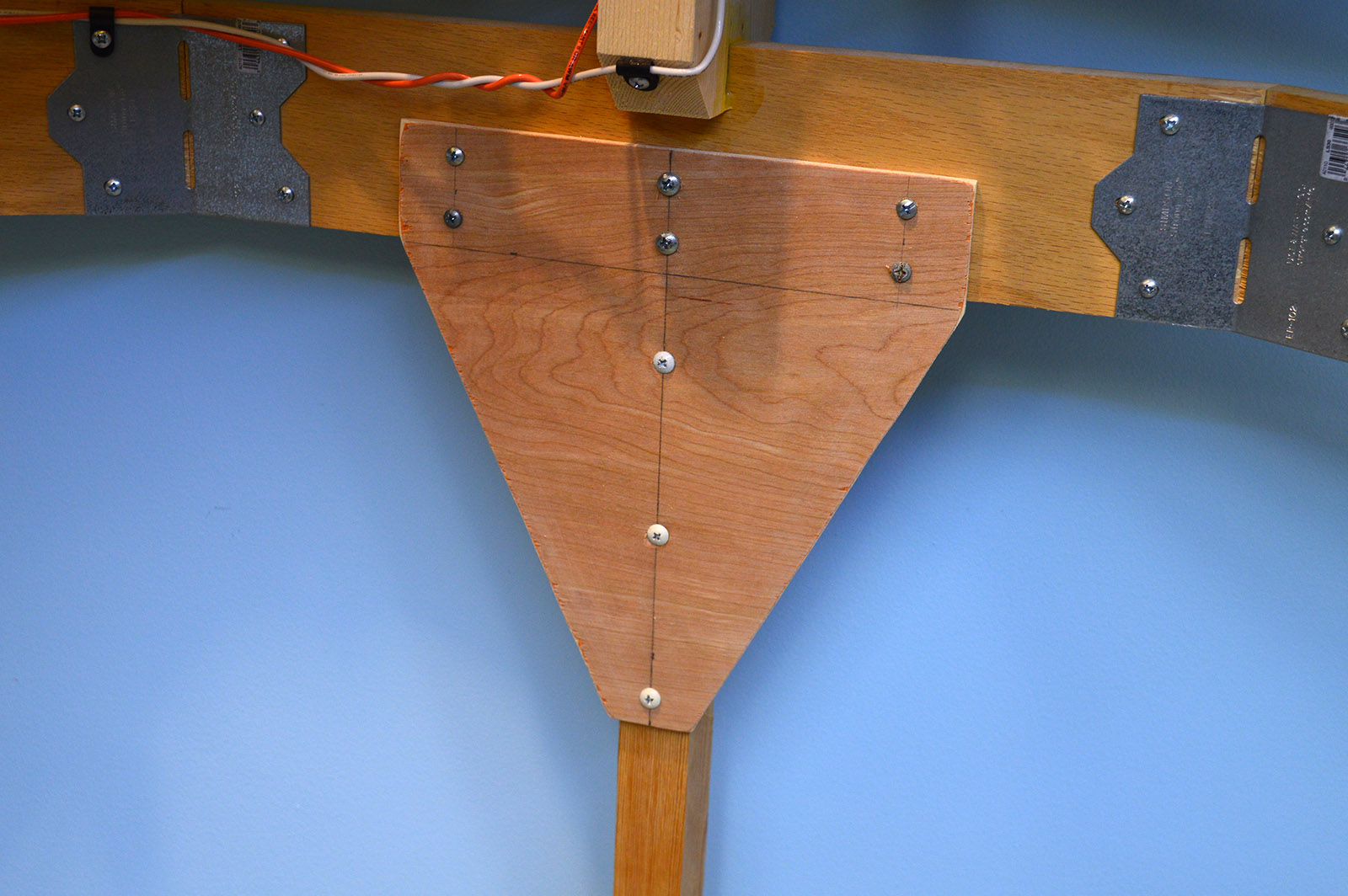
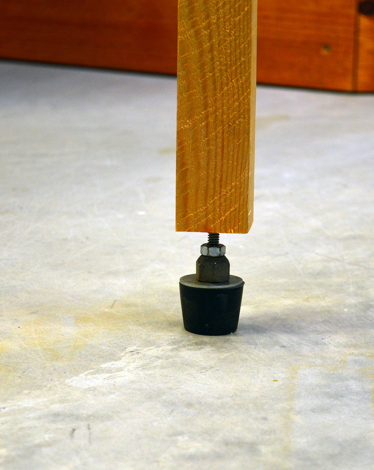
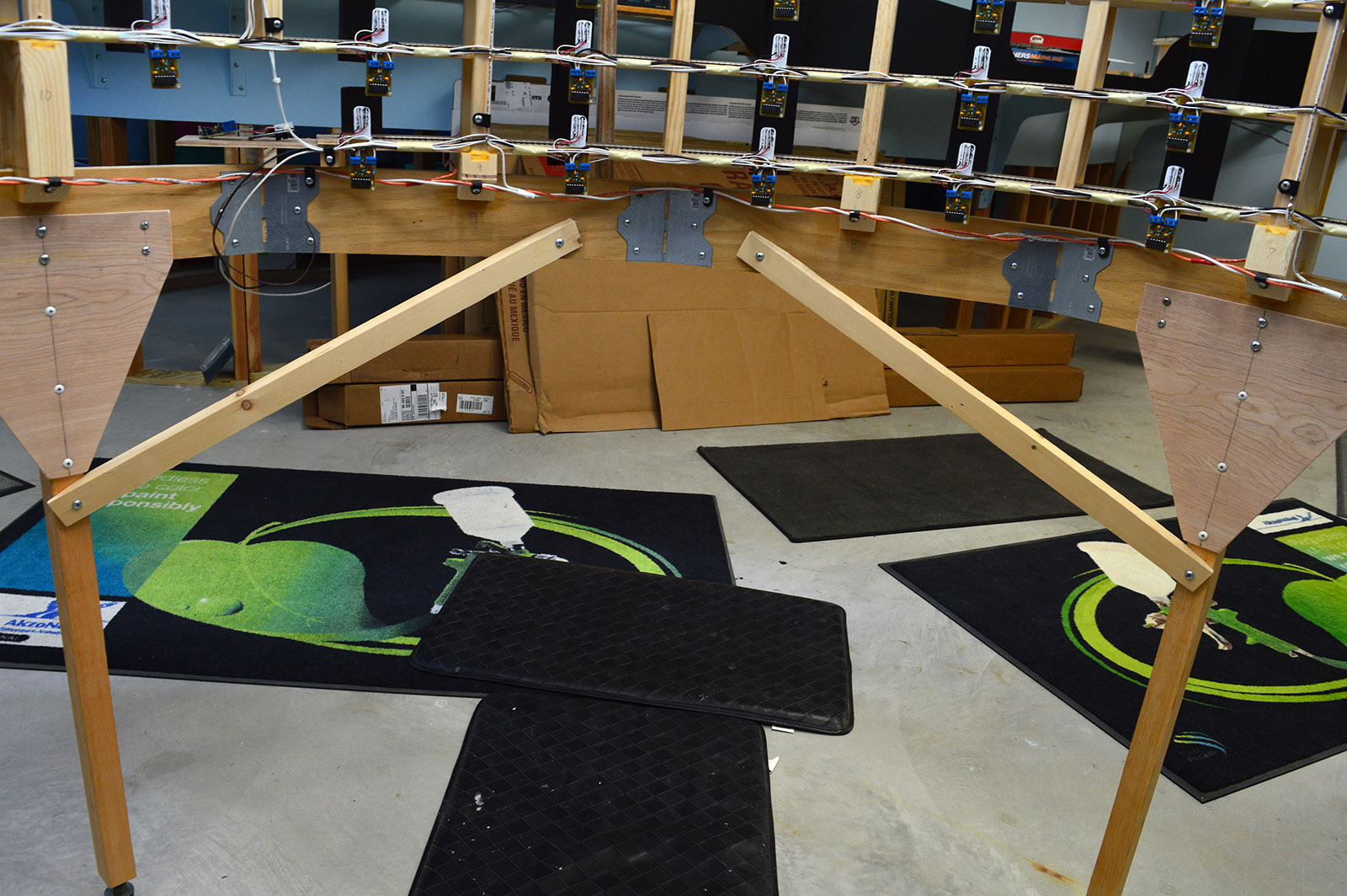
I scrounged around the shop for something from which to make legs. Settled on four legs, each a 2×2 with a stiffening plate made from thin plywood. The top of the 2x2s were notched to fit under an abutment. The two top center screws through the plate engage the 2×2 clamping everything tight against the helix frame with the weight resting on the notch. For adjustability, I fashioned feet from drilled out rubber stoppers, fender washers, rocker nuts from a big inch Pontiac motor as spacers, 1/4″ bolts and nuts. Double stacked nuts were epoxied into holes drilled in the bottom of the 2x2s. Presto! Leveling legs made from odds and ends. Out came the 4′ level and the helix frame was adjusted to sit square and level.
Layout Support
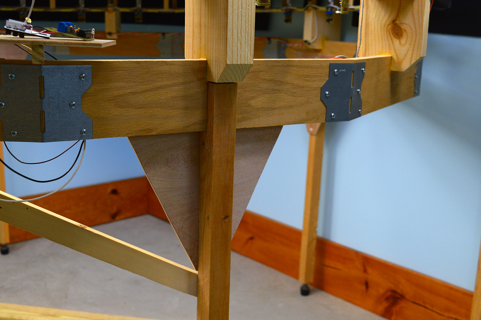
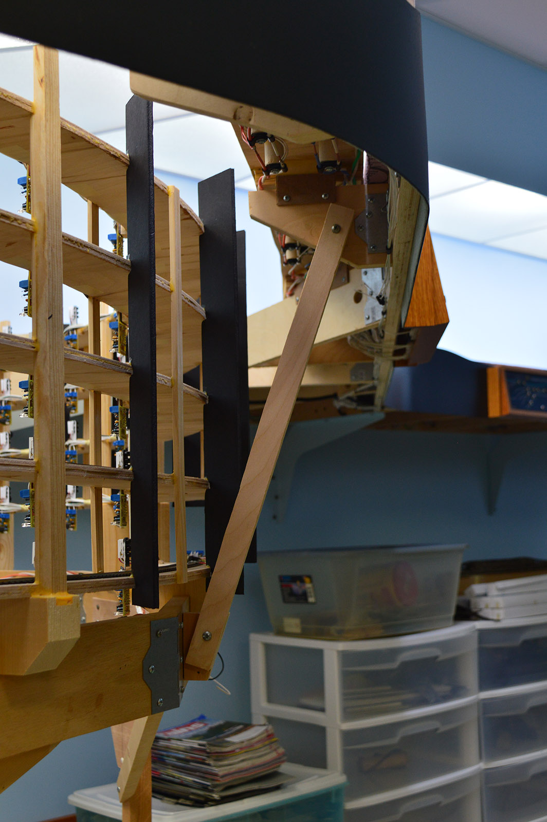
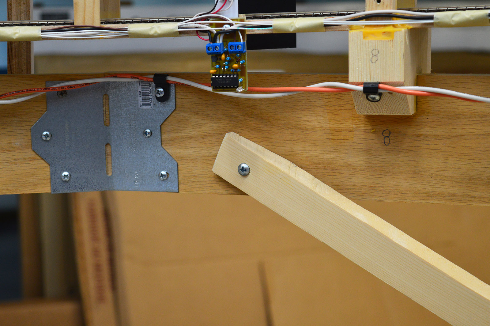
While there are big shelf brackets supporting the layout on either side of the helix opening, the benchwork span of six feet between them is too long to go without support. For years now (since 2012, can you believe it!) that support has been a post temporarily clamped in place.
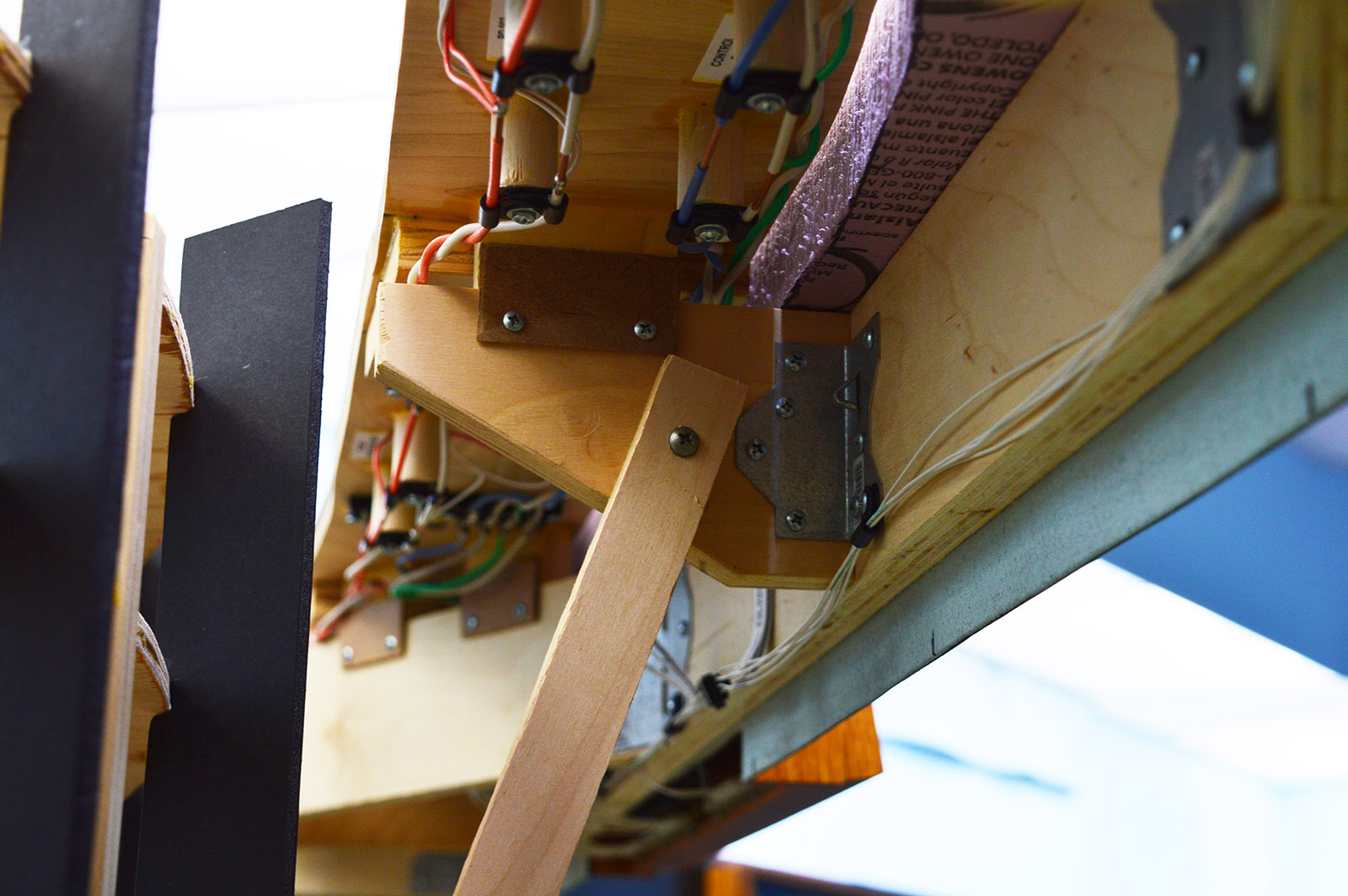
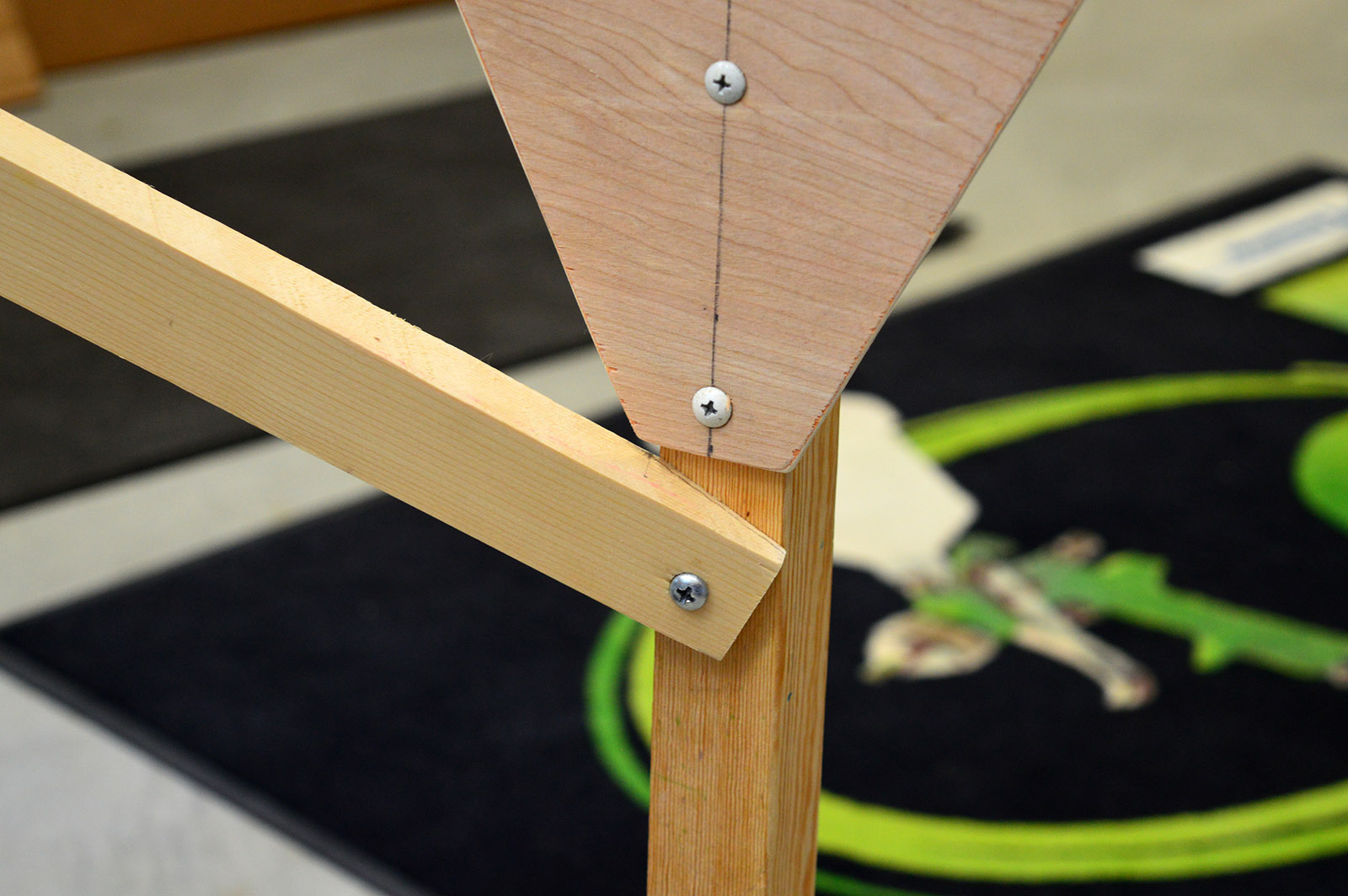
That temporary post is finally gone. Support for the benchwork is provided by the helix base and legs. A bracket attaches the benchwork to the helix base. The load is then transferred to two angled braces connected to the legs so the helix base doesn’t actually carry the load itself. Making the angled braces was somewhat tricky due to the compound angles involved. I rough cut them with a miter saw and then final sanded the angles. A bit tedious but without a ridiculously difficult to make jig I know of no other way to cut the angles. Made a lot of sanding dust but eventually sanded them to fit nice.
Top Entrance Connector
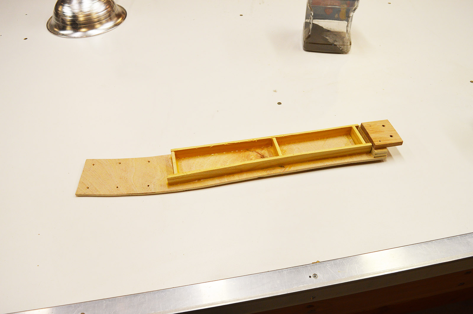
The main running out of the west end of Brittain yard passes through an opening in the backdrop on a connector “bridge” to the helix. The bridge not only connects the helix track to the layout, it also serves as the horizontal curve transition from tangent to the helix 32″ radius and vertical curve transition from level to 2% grade.
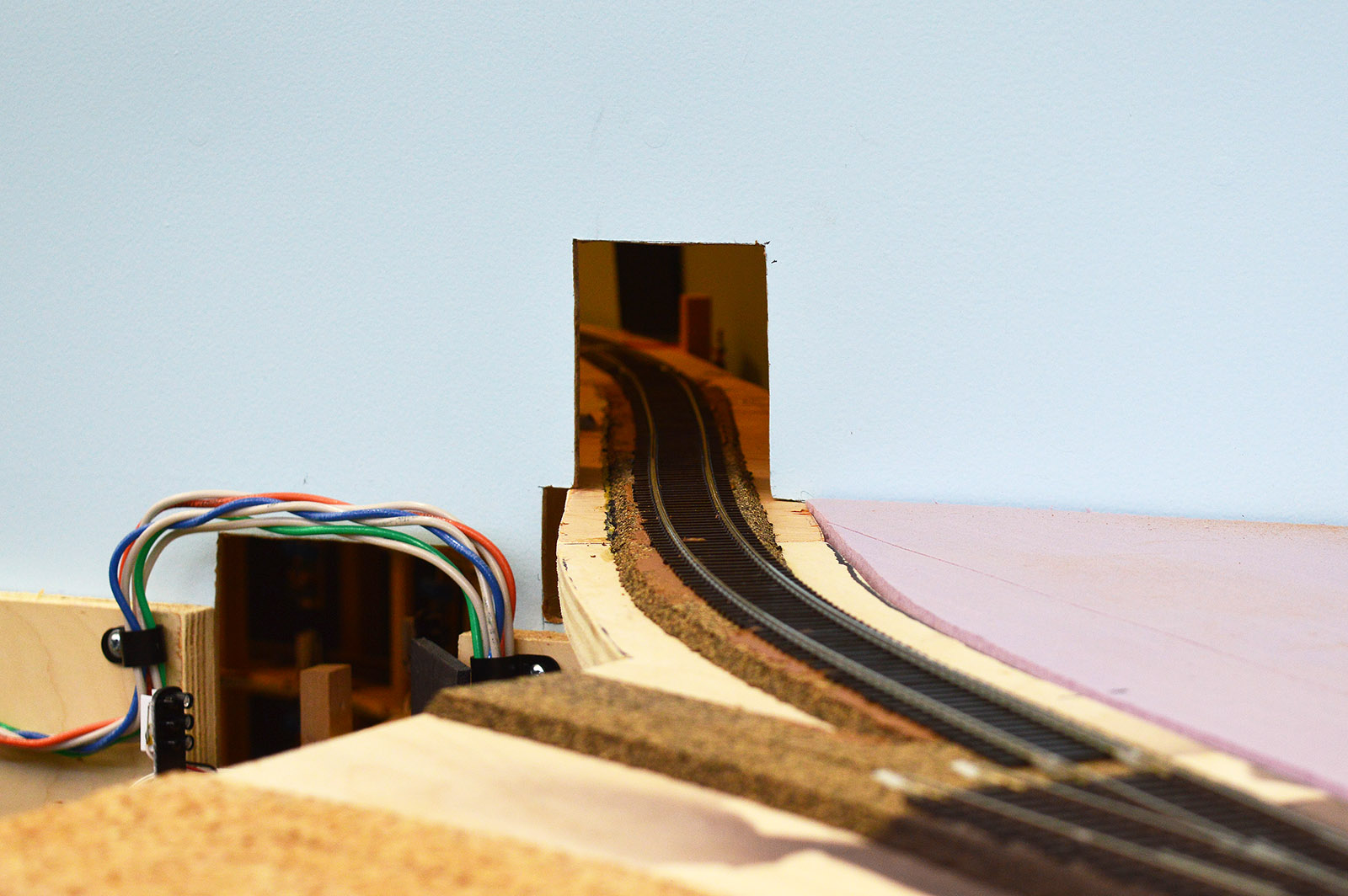
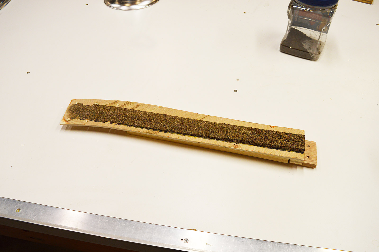
A crude (emphasis crude) cardboard template was made from which I cut a piece of thin plywood. The ends were fabricated so as to attach to the helix roadbed on one end and the layout module sub-roadbed on the other end. The vertical transition was achieved by sanding the profile into cork roadbed glued to the bridge. Vertical ribs were glued to the underside to prevent the thin plywood from warping over time. Track was glued down with caulk and rail joiners soldered. A location sensor was mounted to the side of the bridge and wired in. The single hole mounting of the sensor array and circuit board came in handy here. The circuit board would have hung down in the middle of the track below had I not been able to swivel it on the mount. Caught a lucky break there.
Track and Detection Power
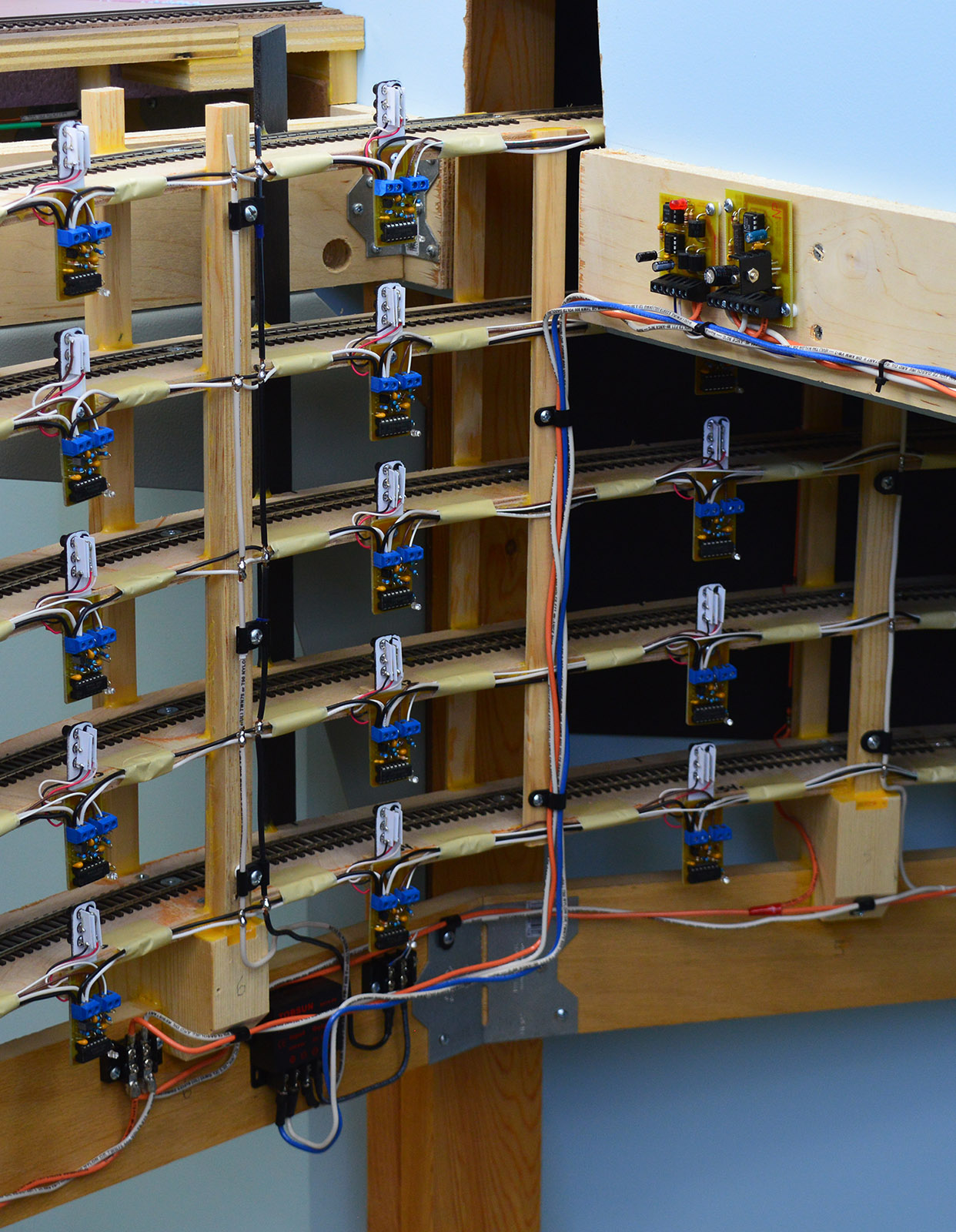
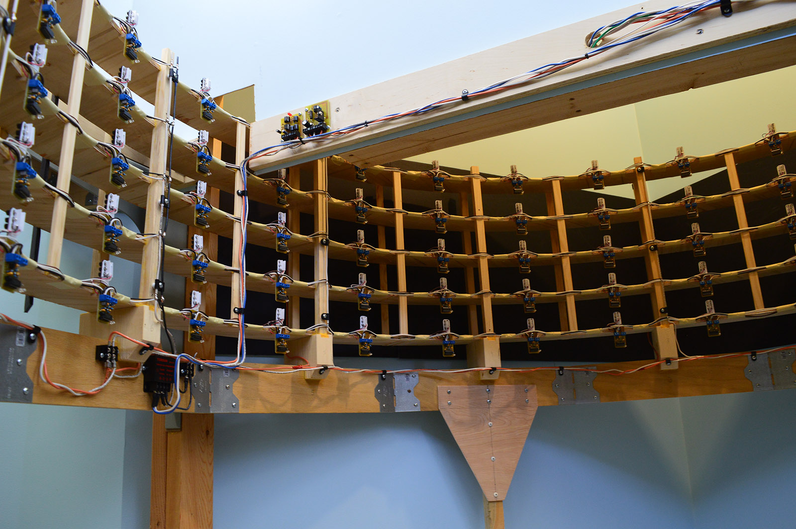
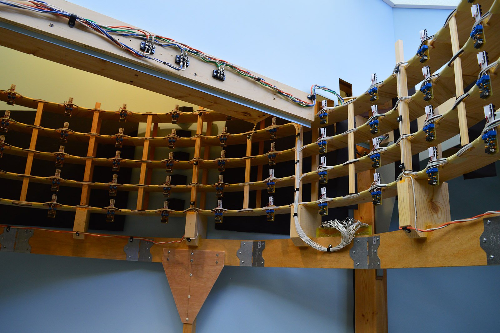
The helix is on its own track power district (orange/white wire). Additionally, it has an occupancy detector for the entire helix including ramps. At first glance it seems odd to have an occupancy detector on a helix that has 116 IR sensors but it really isn’t. I want the signaling system to be completely independent and electrically isolated from the helix location detection system. As far as the signaling system is concerned the helix is simply a long section of track. The circuit breaker and detector are mounted to the benchwork and connect to the helix at a terminal block. A 12 volt feed from the Control bus (blue/white wire) was brought to the 5 volt regulator powering the system.
IR Deflectors
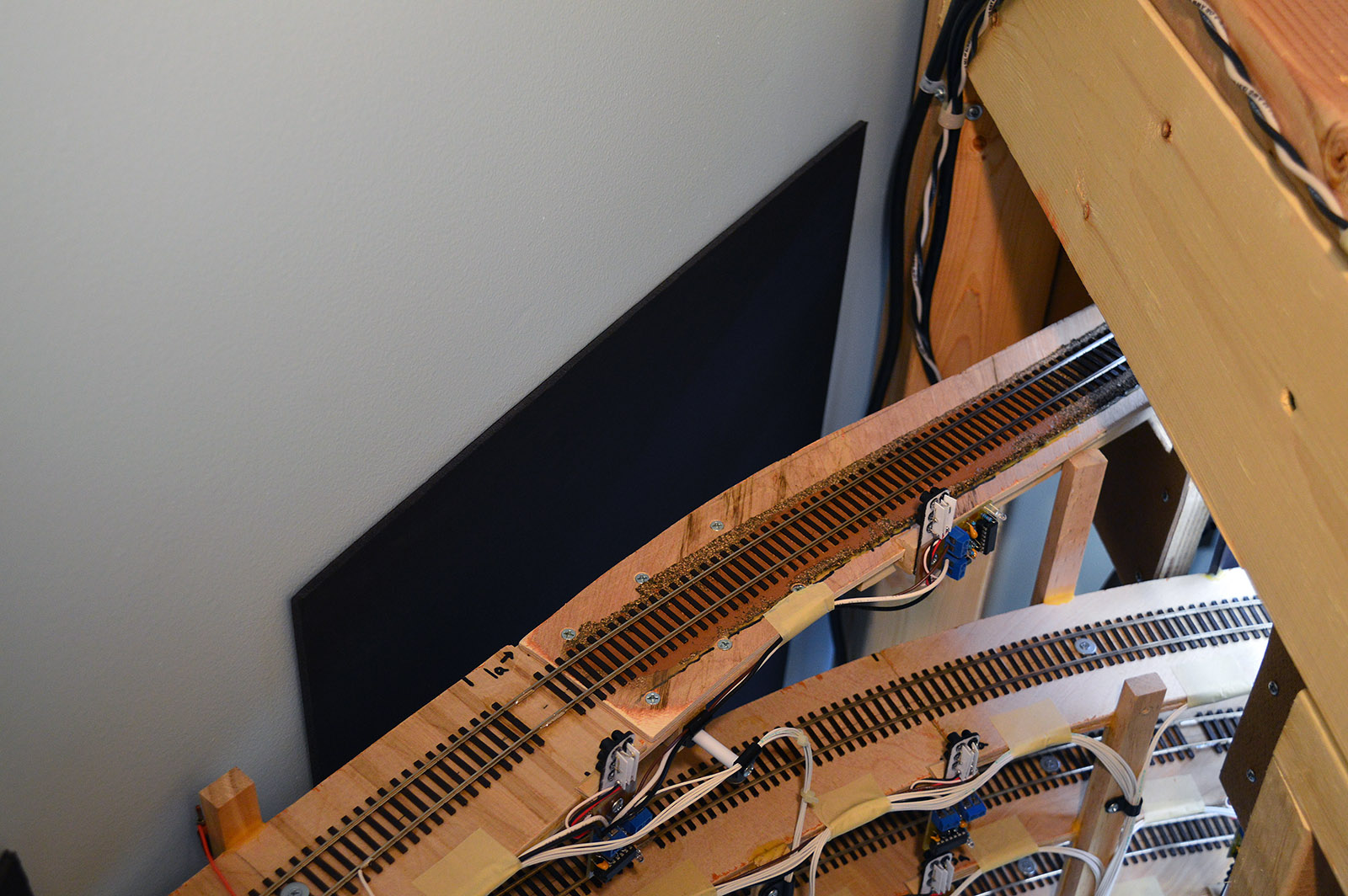
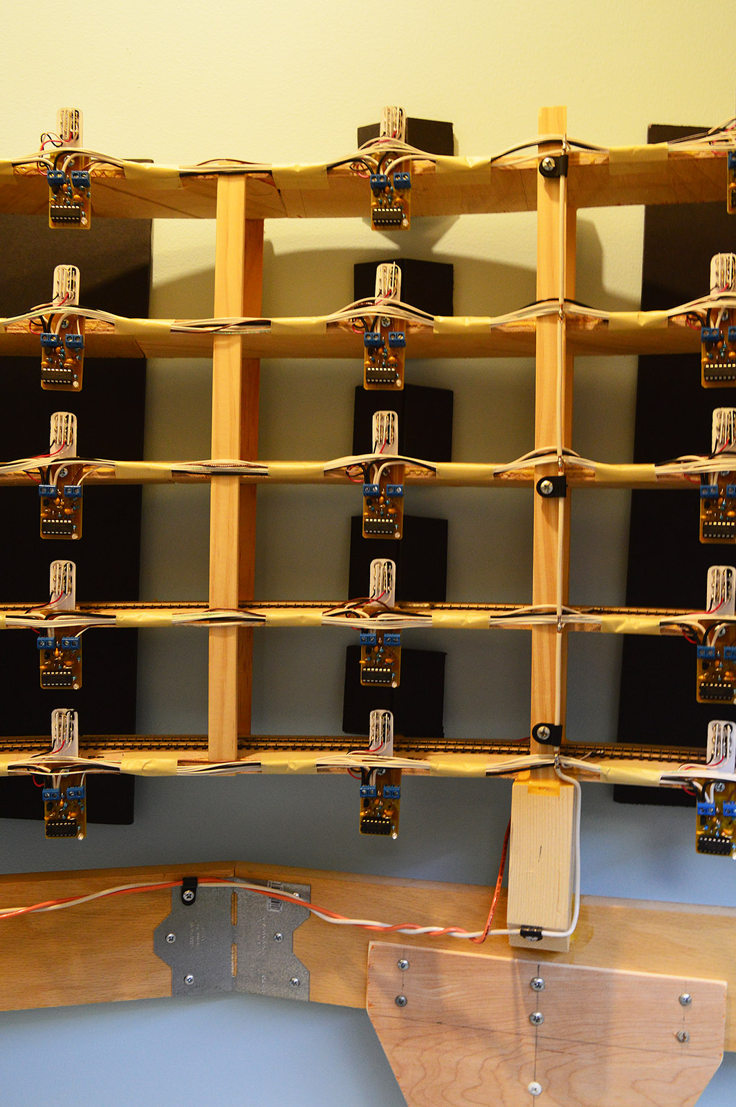
It is a good thing I earlier discovered black Gator board is a good IR absorber. The first time I turned on the location detection I had blue indicator lights galore. The big, flat, sky blue walls of the room corner caused the entire back half of the helix to fire. That was easily rectified by placing sheets of Gator board on the walls. Rolled masking tape on the backside hold them in place.
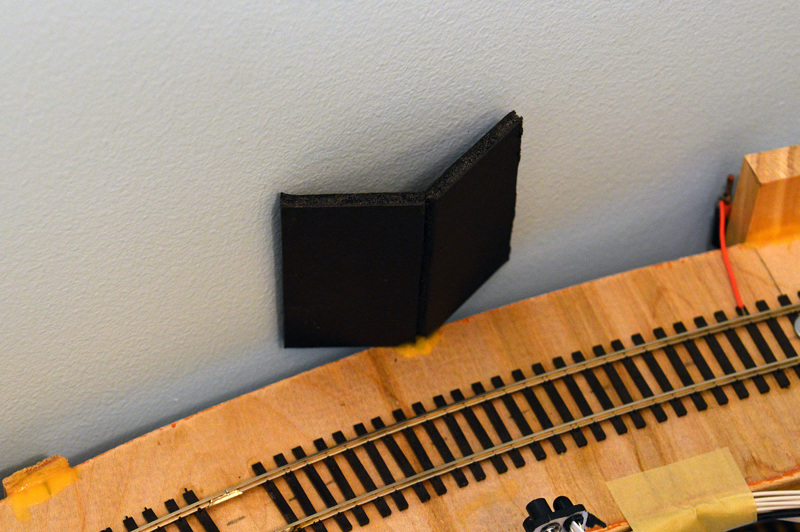
In one particular location the sensors pointed straight at the wall which was right up against the helix. In that instance I had to create a beam splitter arrangement to sufficiently deflect the light in such a shallow space. A blob of wood glue attaches the Gator board to the helix.
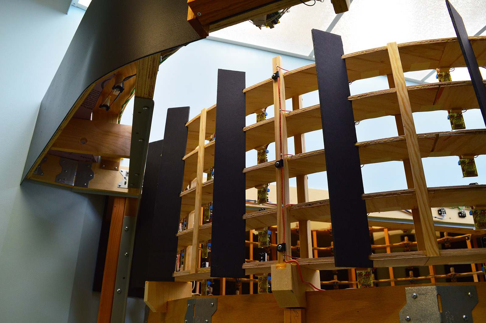
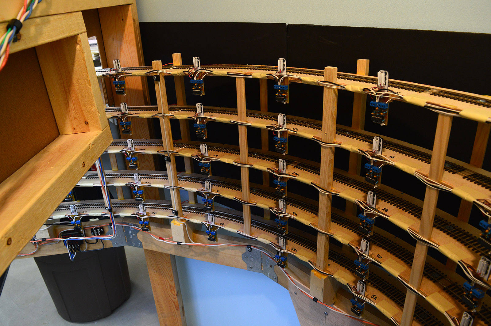
The front half of the helix was a bit more challenging. There were only a few false trigger points caused by shelf brackets or benchwork but since I don’t know what else may be added under there in the future I decided to put deflectors on all.
The deflectors are 19″ x 2-1/2″ vertical strips of Gator board with small notches cut that align with the roadbed. They were slid over the roadbed, angled 45 degrees, and glued in place.

That’s a Wrap
At long last the helix is built and installed. Hoorah! Sadly, at the moment it is a helix to nowhere. The lower deck does not yet exist. I’ll rig up a temporary track extension board at the bottom so I can run a train up and down. But first, I want to build the fascia panel that brings the whole thing to life. I’ll leave you today with a few random helix pics. Back soon.


Another engineering marvel, as usual. Excellent work! Love it when a plan comes together and actually fits! Congratulations.
VERY nice job,…a bit more complicated than i would have built, but you did a marvelous job
Congratulations. Big milestone, I was wondering how the hell would you ever move that thing, it looks so massive. Great job.
Great work. The helix looks superb.
PS. Please come and wire my railroad. Mine looks like a spaghetti bowl.
Great work Alan, huge accomplishment getting the helix in, another major milestone in the LK&O build…
Thanks to everyone for the compliments. The helix has been a fun build.
I have just binge watched your entire series, and scanned through the Helix Sense set again. No one asked the question I have, which is why you chose to use the reflective approach with the sensors rather than placing them on opposite sides of the track and having the train break the beam. From researching these devices, placing them at an angle to the track (not 90 degrees) provides longer coverage and would not require multiple sensors at each location. The amount of wiring would be the same and the Gator board might not be needed. Your work is amazing and beyond my skills and knowledge. Keep it up. Looking foreword to more.
Joseph, To answer your questions…
a. I used the reflective sensors because I wanted all the sensor hardware on the inner diameter. There is virtually no access to the outer diameter on the back half of the helix. Break beam sensors would have required hardware on the outer diameter.
b. 90 degrees is the optimum angle for reflective sensing. Break beam types do provide greater sensing distance by slightly “shooting down the track” but break beam wasn’t an option for me.
c. The original number of sensors corresponded to the the desired granularity of the LED display – 60 increments. It was determined that gaps might appear on the panel so the sensor count was doubled to 120, combining them into pairs to preserve the original 60 increments.
Refer to the “Long trains short trains, fast trains slow trains” section of this post https://lkorailroad.com/helix-sense-part-ii/ for more detail.
Note: the final product has 58 increments instead of 60 due to the last loop being slightly less than a full loop.
Thanks for following along Joseph.