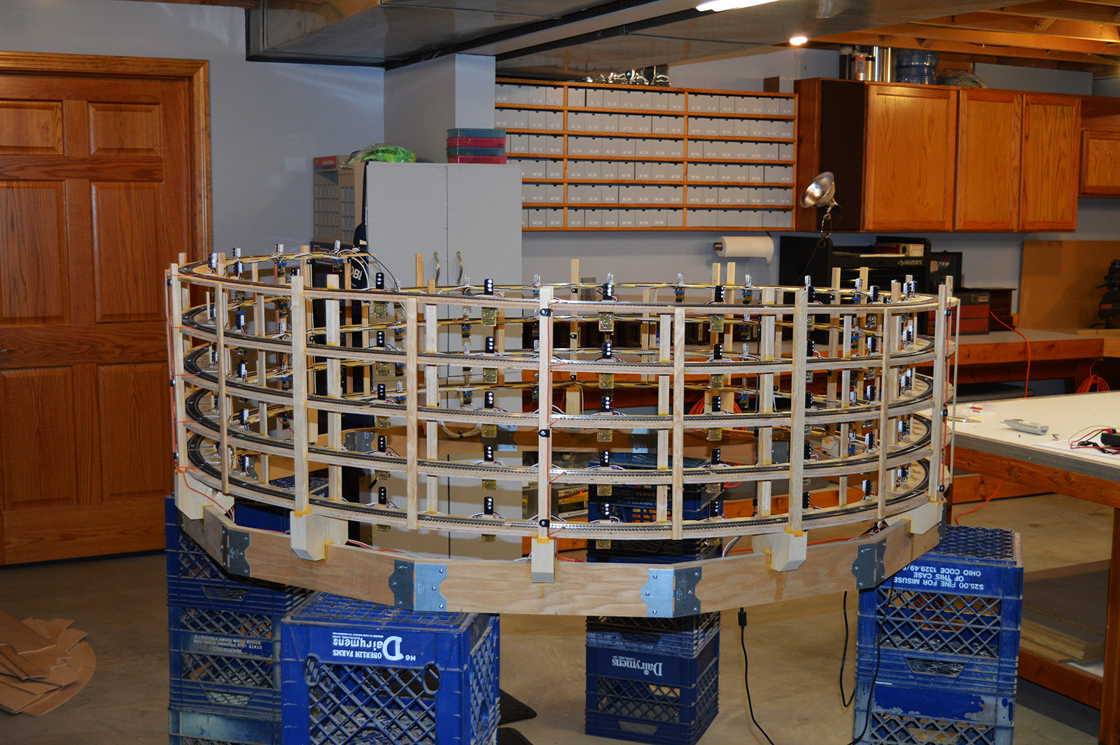
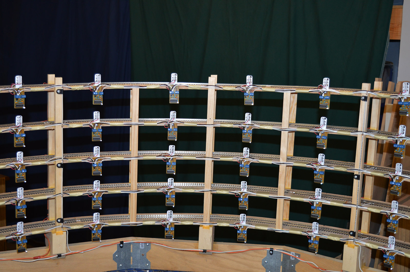
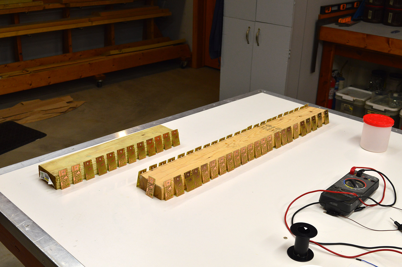
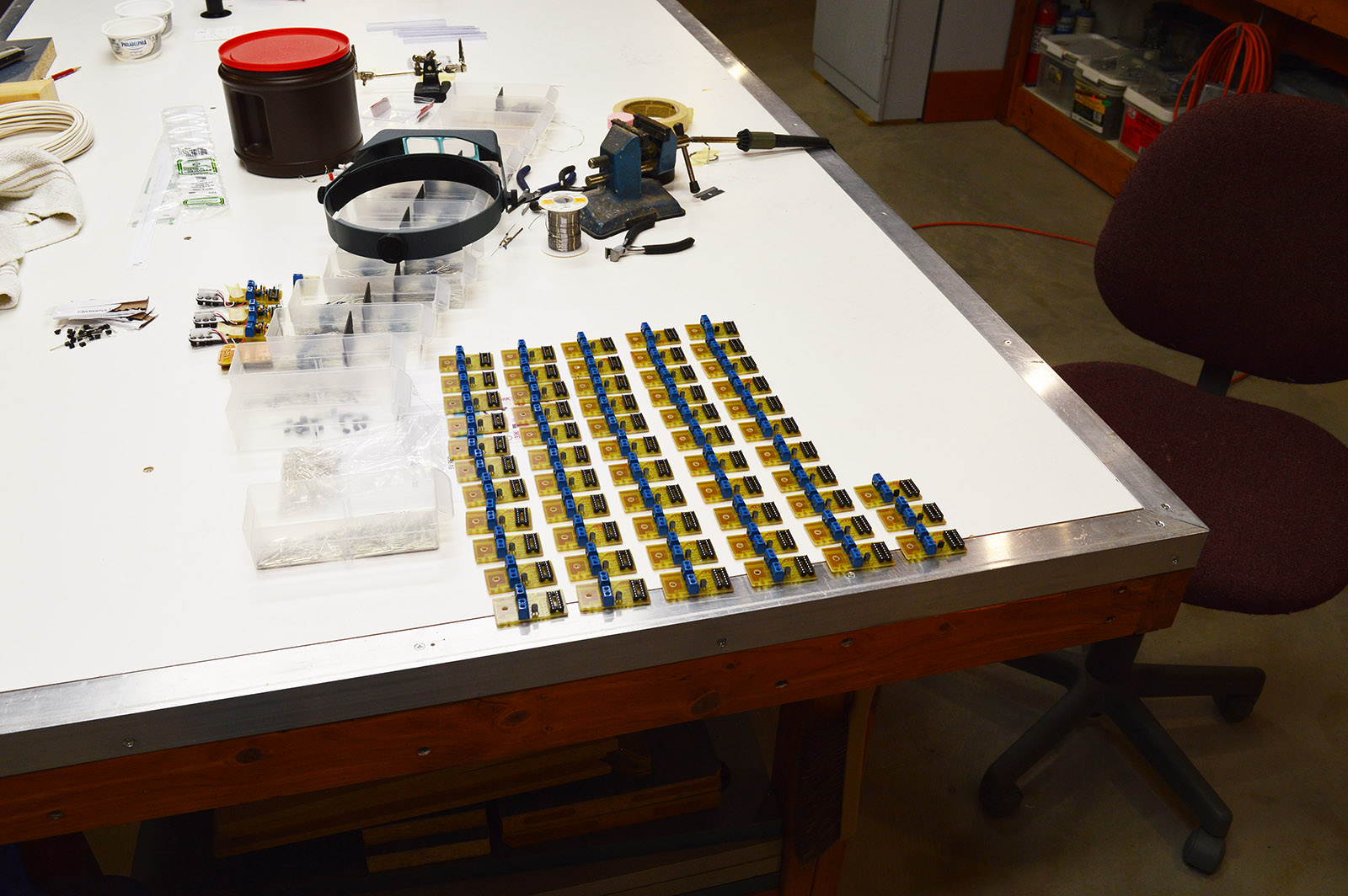
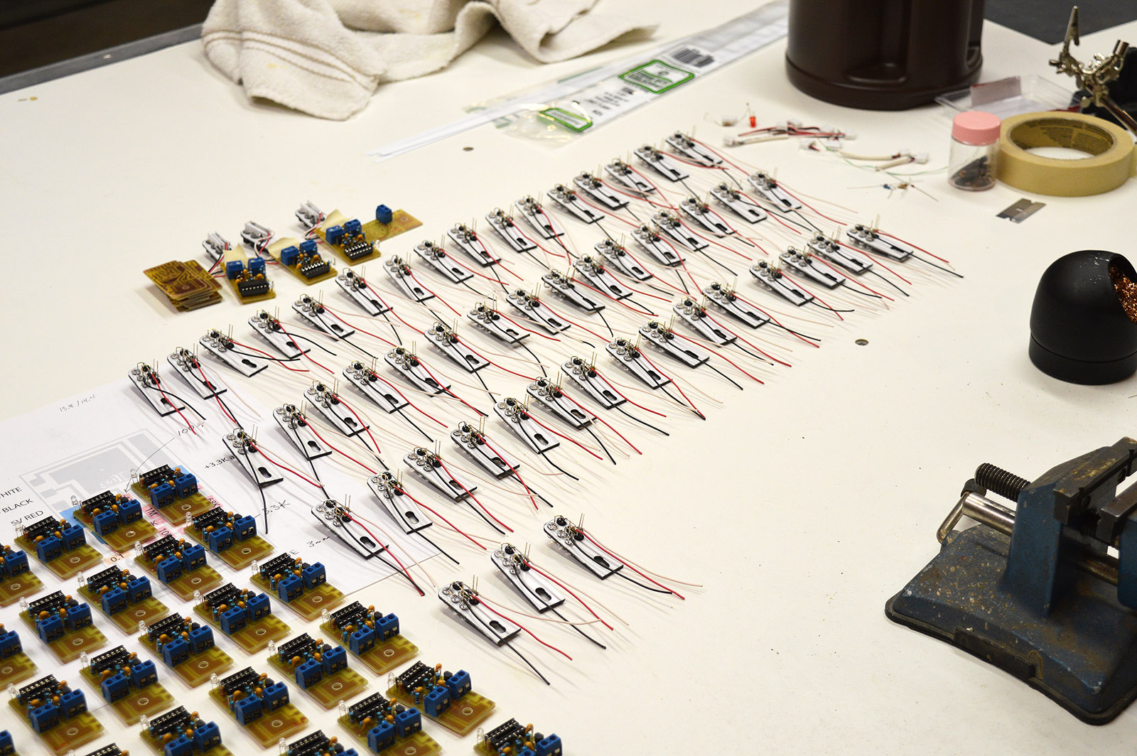
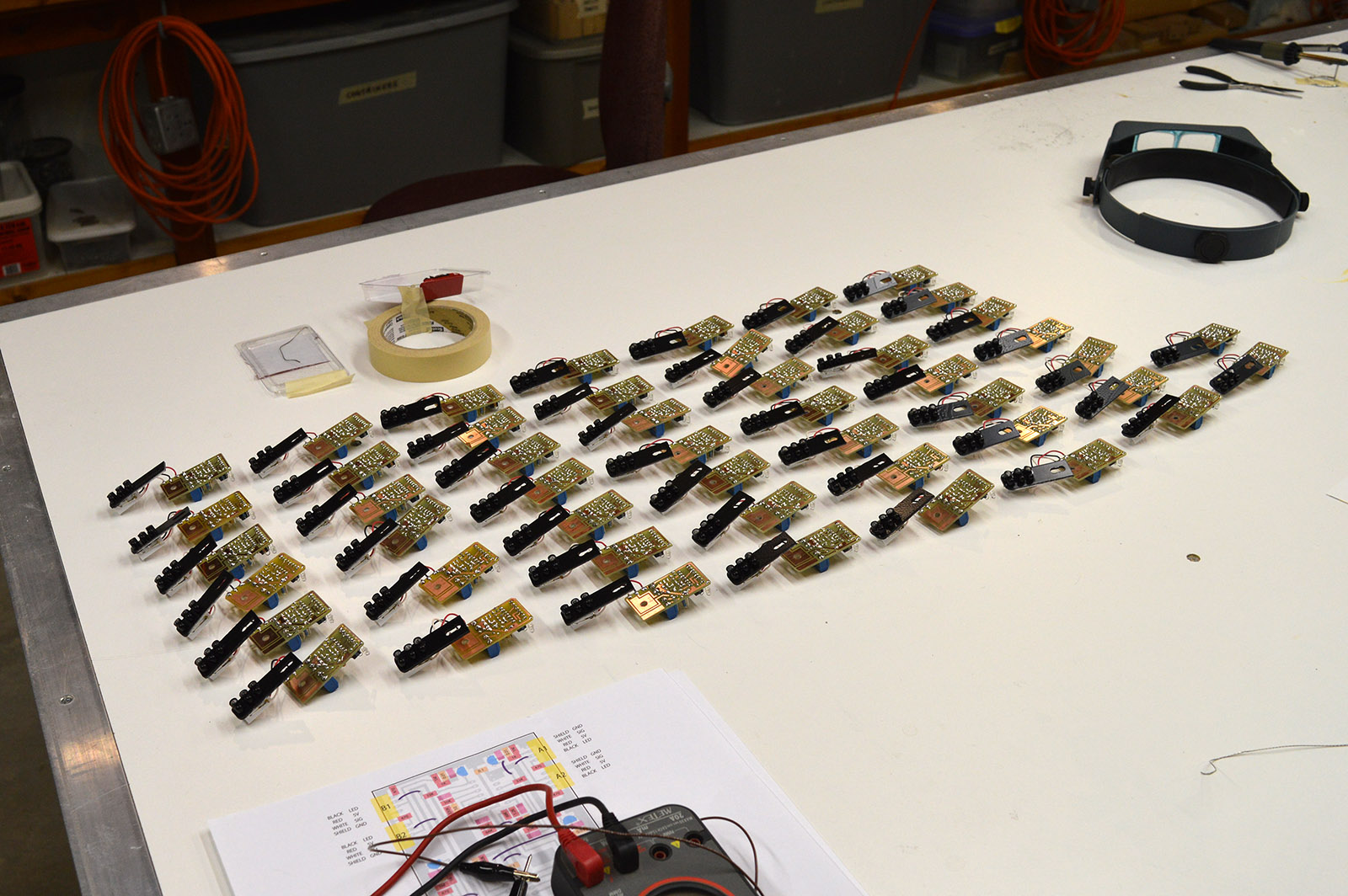
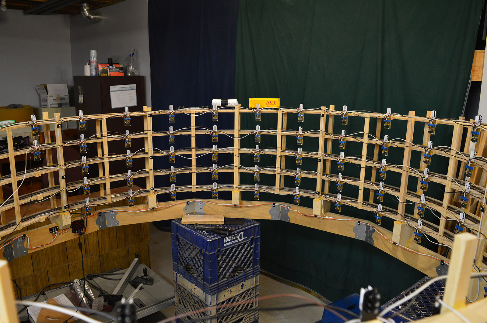
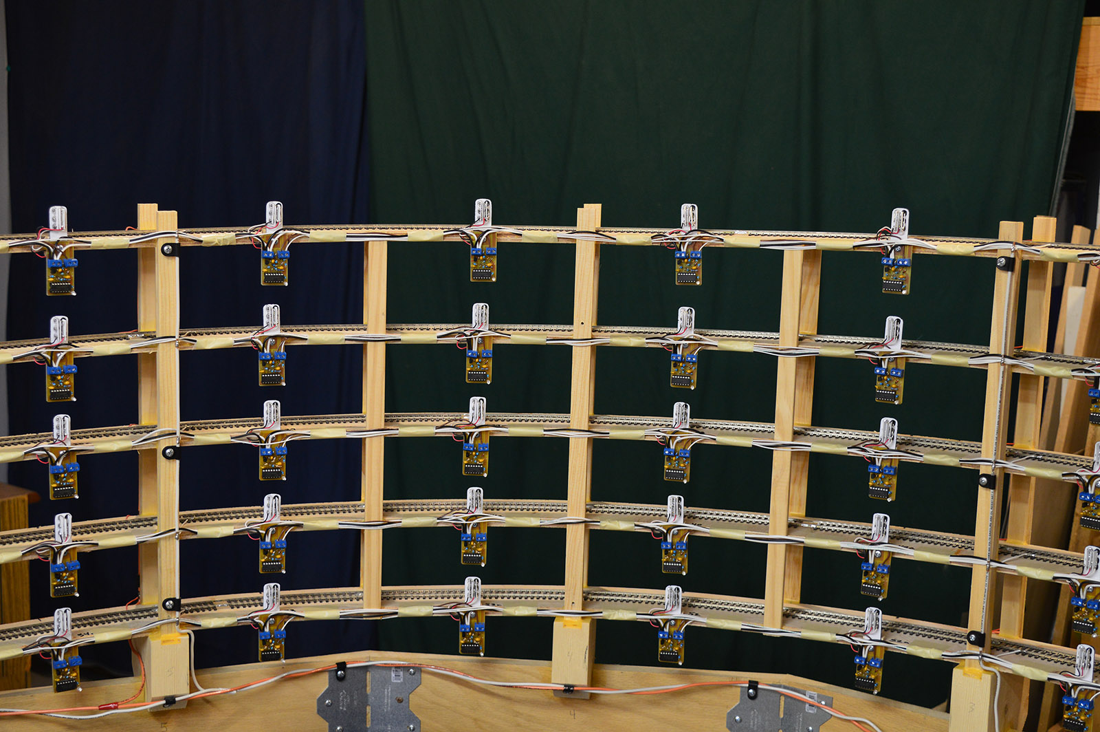
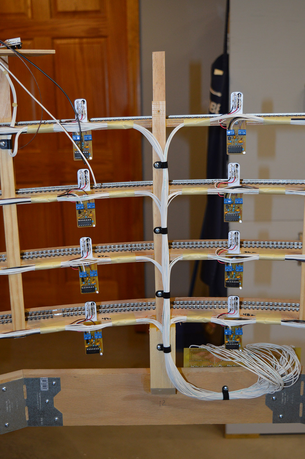
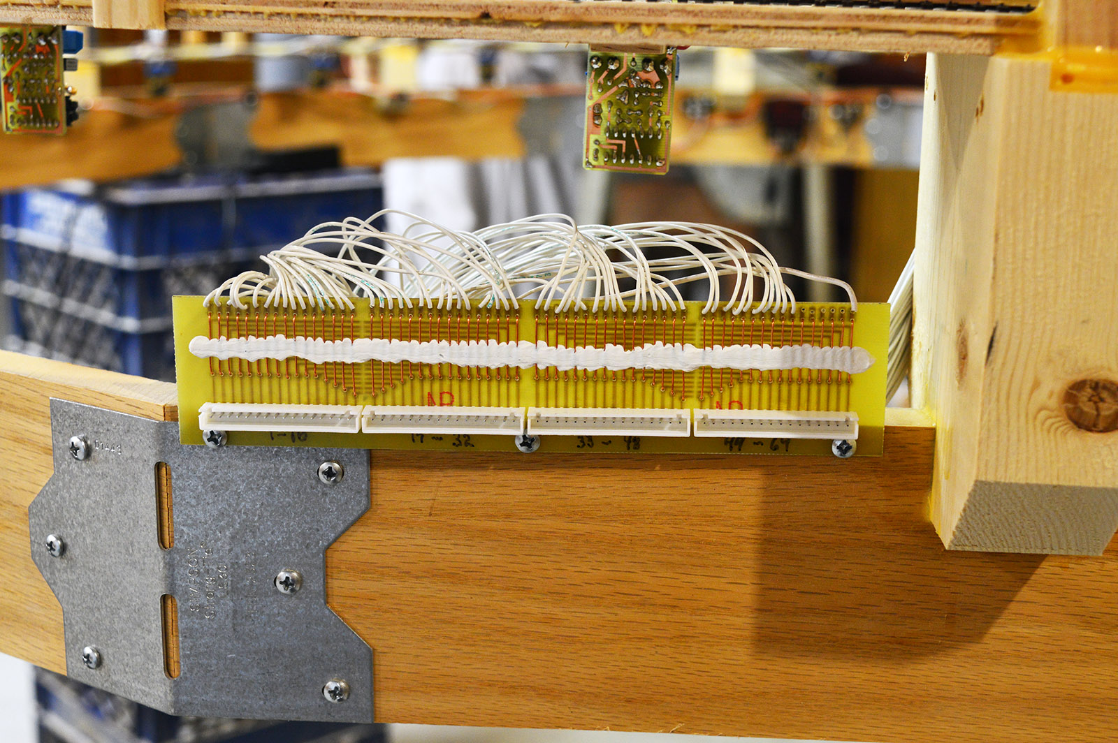
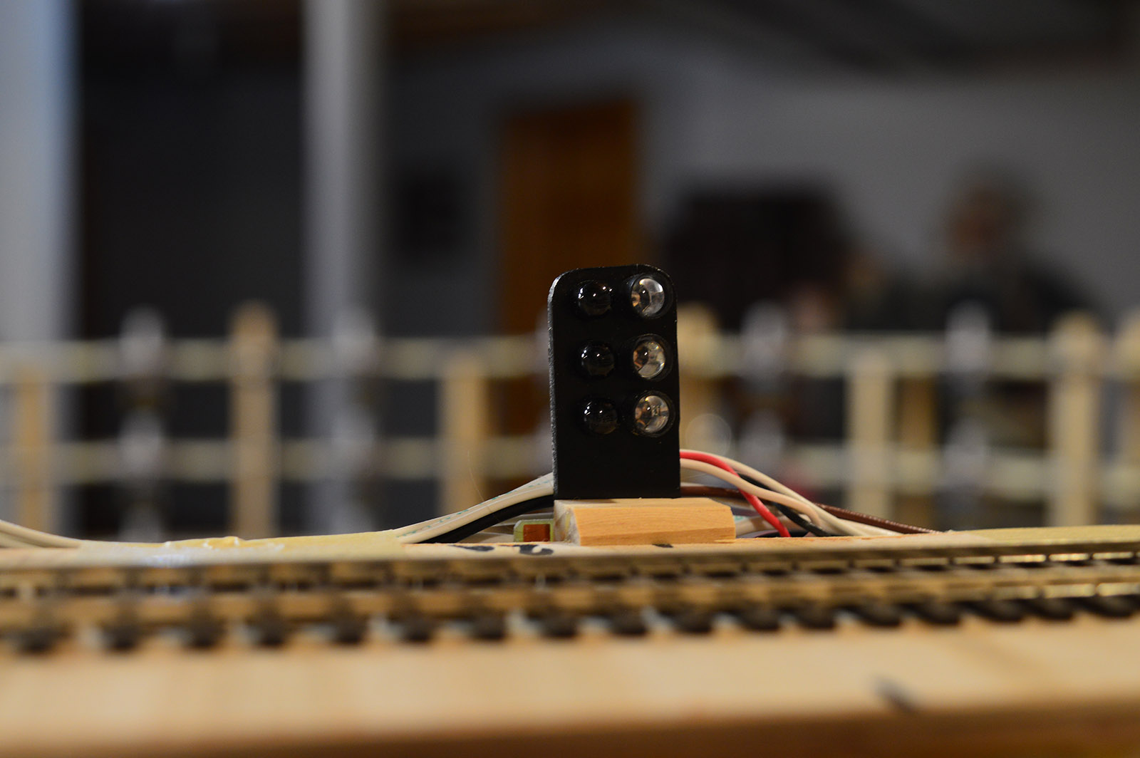
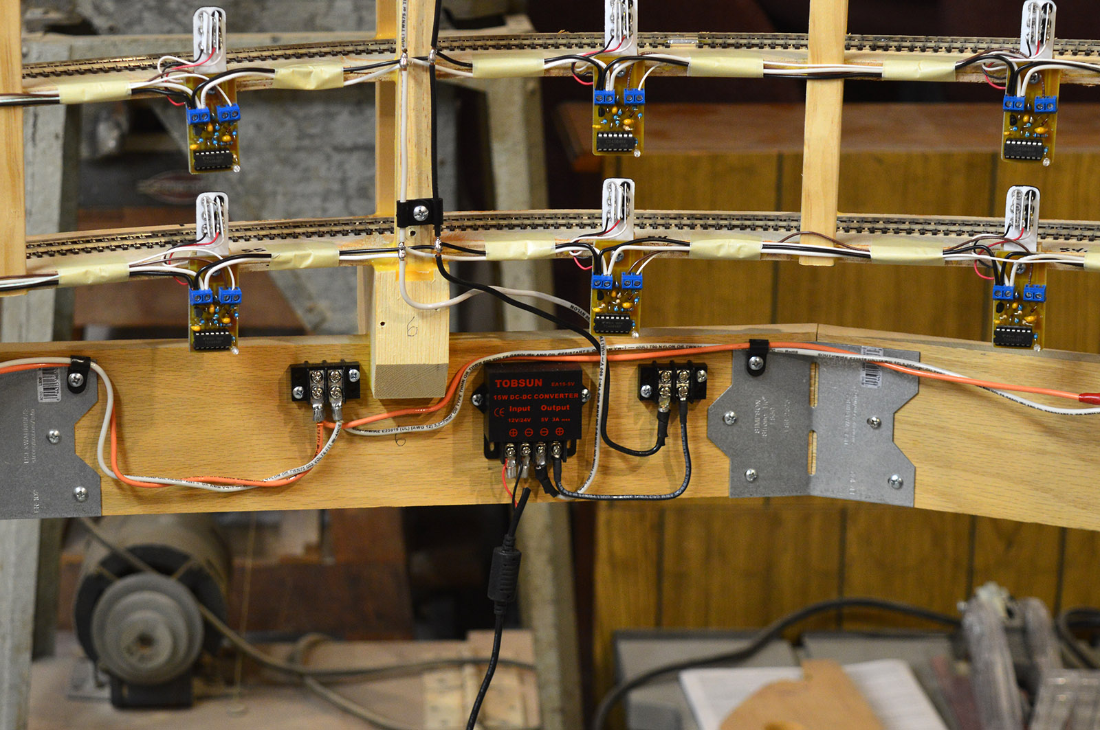
At long last the helix is finally complete and ready for installation into the layout. All the location detector electronics are tested and working fine.
If I ever tire of model railroading I have a good start on a scale model of the Large Hadron Collider!
A few final pics of the build…


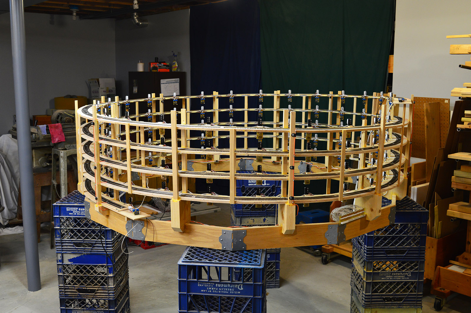
Time to move this thing into position. May have to call on Al Quiring and his D9 to give me a hand with the move!


Your work is amazing and inspirational!
As always, SO neat/tidy/professional. I am going to have to go back aways to recollect the reason(s) why so many detectors were required, and why they had to be so closely spaced. I can’t remember seeing any other helix that needed to be so extensively monitored. But again, great work Alan. It’s nice to see that you are still plugging away.
Thanks Dennis.
Dwight, Part II explains why so many sensors.
So. Nice work finishing off the helix…Now, how the heck are you going to move that? Was it not possible to build the helix in situ? and you have another one to build, right?
Clark, sit tight until the next post. It will answer all your questions.
Your work is really inspiring. I do have a question about why you choose this method over current sensing via the rail? I see advantages and disadvantage for both, but I am interested to hear from someone who walked a mile in those shoes.
Great work.
Good question Art.
Current sensing would have required many insulated rail joints in the helix. I prefer not to use insulated joiners on a curve unless I have no other choice. When insulated joiners are used in a curve there exists a potential for slight rail misalignment whereas there is none with soldered joiners.
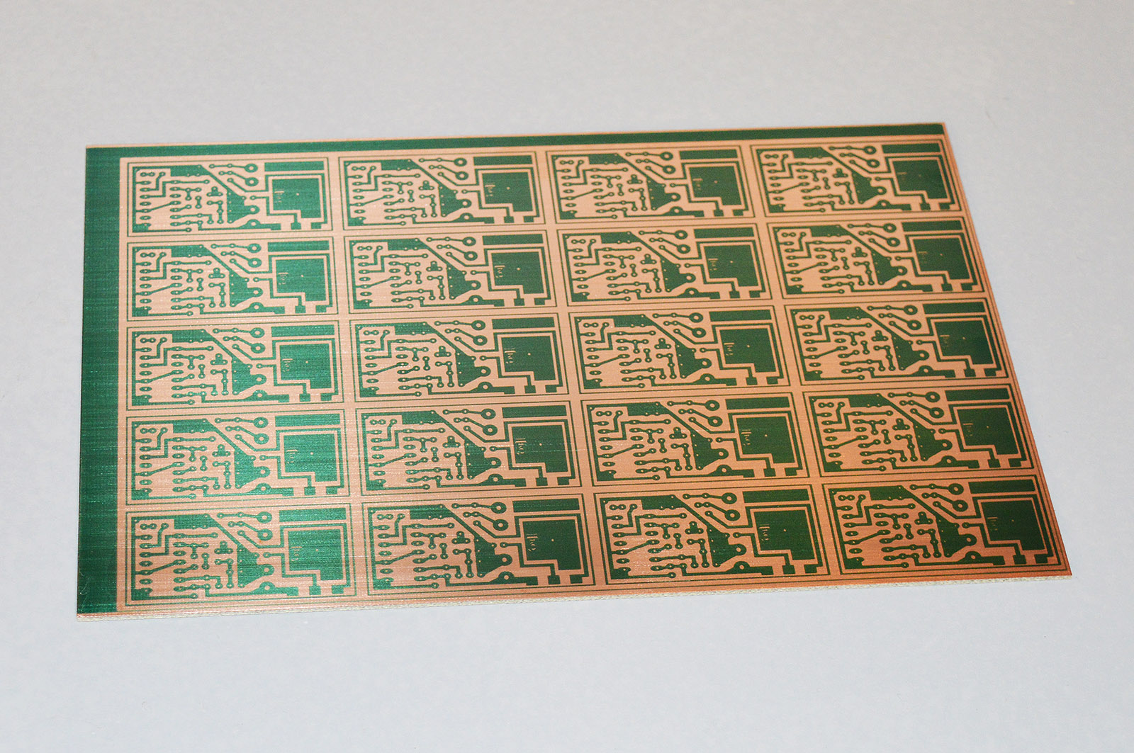
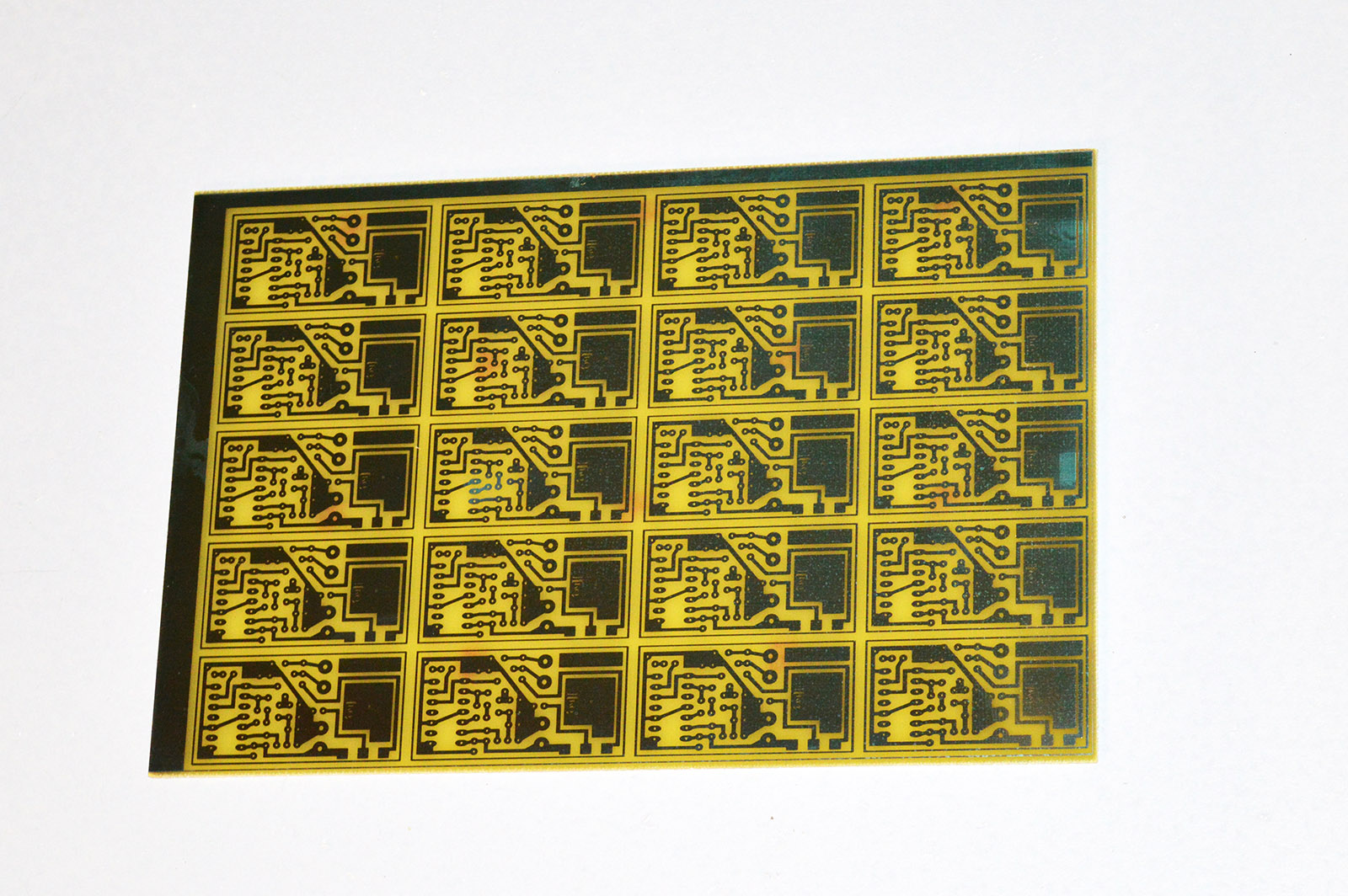
On the plus side, current sensing would have cut in half the number of sensors required – 29 instead of 58. The IR sensors, while tedious to solder together so many of them, were actually quite inexpensive to build so quantity wasn’t a contributing factor in the decision.