The previous post described the basic sensing circuit and its theory of operation. This post outlines the modifications to make it function reliably on the helix.
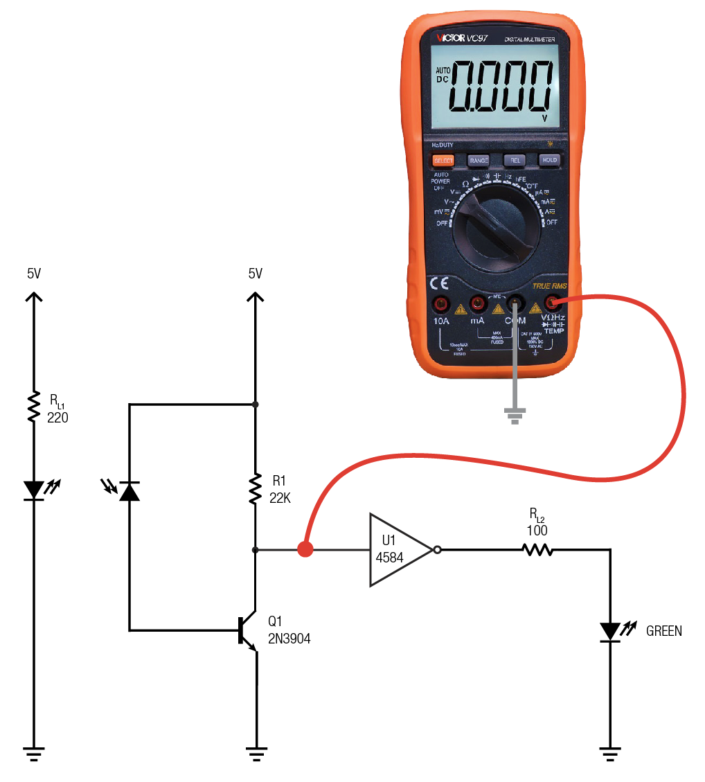
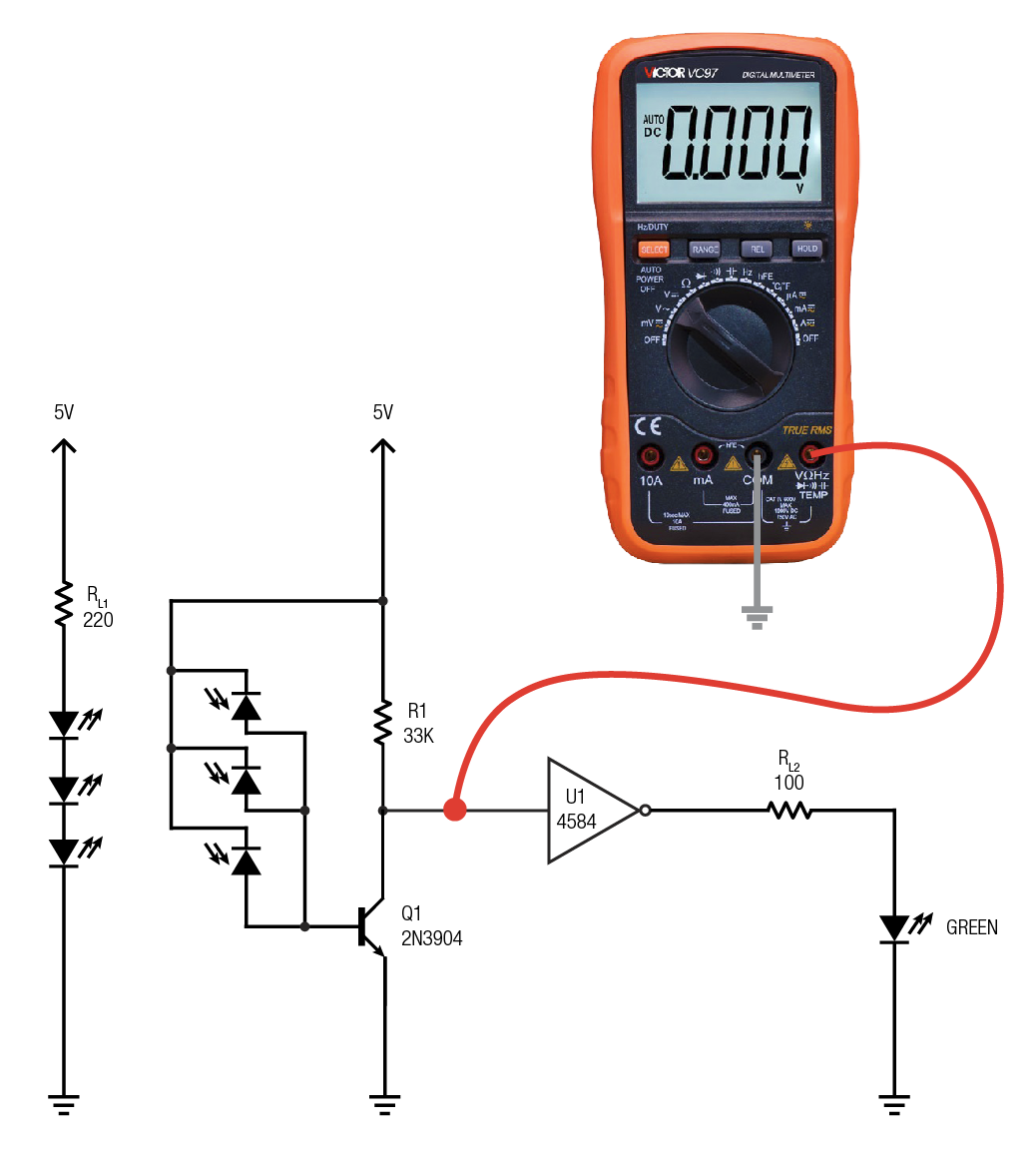
The basic circuit was constructed on a breadboard and a test track set in front of the emitter/detector the same distance as it will be on the actual helix, about an inch away from the car sides. A sleeve of heat shrink tubing was placed over the IR LED so it and the photodiode could sit side-by-side without triggering. My voltmeter was connected to the input of U1 so I could measure the voltage present at the gate input. The Schmitt input has thresholds of 2.1 (falling) and 2.7 volts (rising) so the circuit must be able to swing past these values in actual operation. Preferably, swing past these values by a wide margin to ensure reliable operation with no false triggers. I chose less than 1v (falling/detect) and greater than 4v (rising/no detect) as ideal target values. Starting component values have been added to the schematic.
Here we go!
I was pleasantly surprised by how well this simple little circuit worked on the first go around. To be honest, I wasn’t expecting round one to get so close to the objective. There were, however, a few issues that needed to be addressed.
- Sensitivity to room lighting
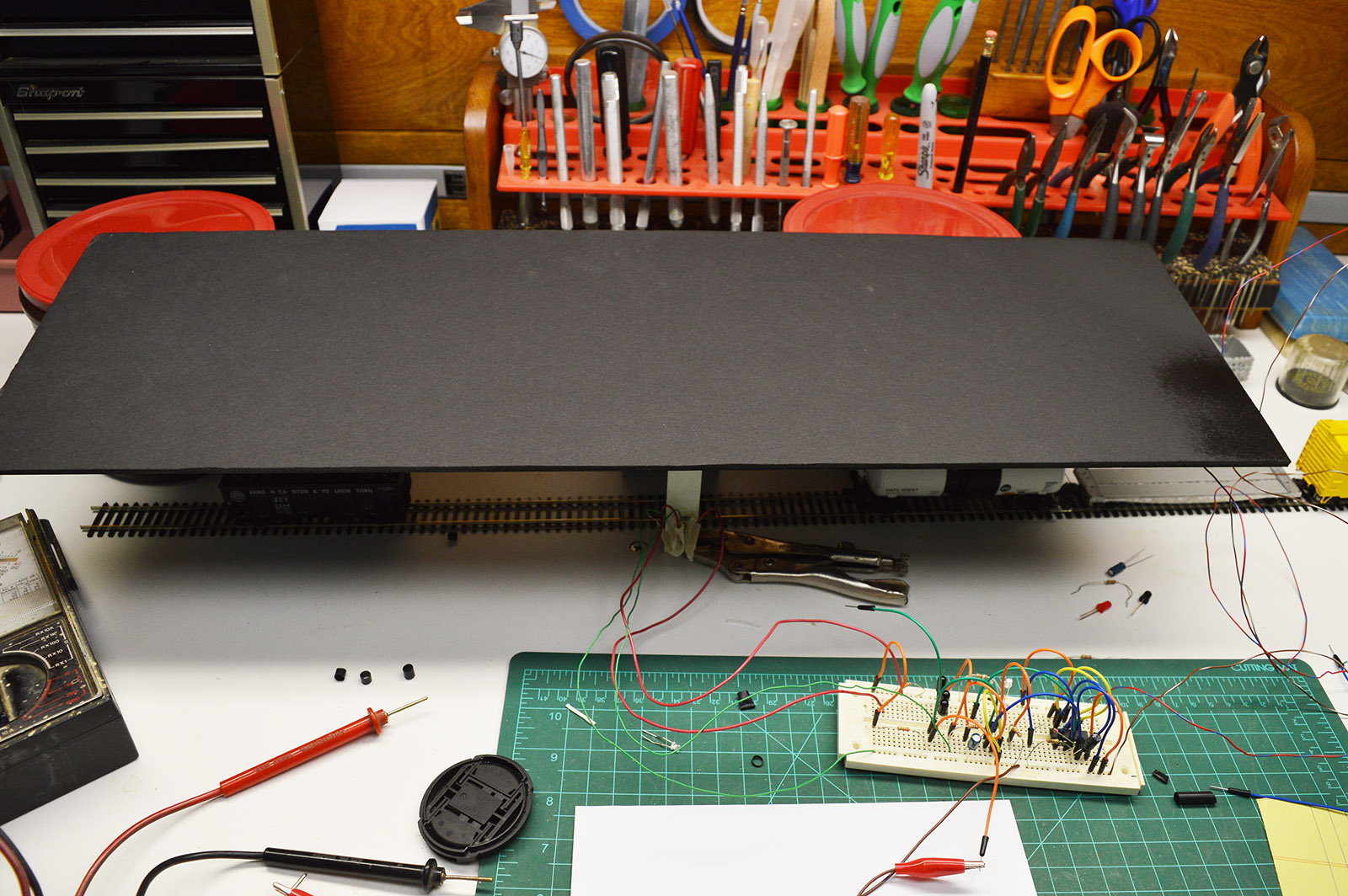
This was not unexpected but I was taken aback by how much it was affected. The voltage readings varied greatly with only slight changes in sensor angle within the florescent lit train room. The room lighting was enough to pull the gate voltage below 2.1V at times and had a maximum dark voltage of only 3.2v. If the circuit were being used anywhere but a dark place this would be a show stopper. Makes it easy to understand why TV remote controls are modulated IR instead of steady state IR. Fortunately, the helix will be in a dark place under the layout behind a drape. I placed a piece of poster board over the test setup to mimic the light level of the helix area. Problem solved. - Sensing distance too great
My IR LEDs are typical 20mA, 1.2 forward volt diodes so I started off with a 220 ohm resistor yielding a current of 17mA. The sensing distance went out to almost 30″ with the LED running at this current level. Much too far considering there will be many of these LEDs shining from the helix. A helix full of emitters blasting out this much light would make a big glowing blob with IR light bouncing off of everything. Clearly the LED current needed dialing back. RL1 was changed to 680 ohms limiting the current to 6mA. That reduced the max sense distance of the target (my finger) to around 6″. Problem solved. - Object color, shape, and material makes a big difference
This one surprised me, especially the material. I had falsely assumed the color of objects would make only a small difference because I’m using IR. Wrong. Color makes a big difference. A yellow boxcar has a much greater reflection than a black boxcar. The sheen of the color also played a role although not as you might expect. Glossy was highly reflective however oddly enough, flat was more reflective than satin. Adding to these variances was shape. A flat sided box car reflected well while a rounded tank car had low reflection. As if these weren’t enough variables, the material from which the object is made makes a difference. Plastic, metal, cloth each reflected differently even when they were of the same shape and color. You would think a piece of black velvet cloth would have less reflection than a piece of black plastic but not so. Black velvet cloth reflects very well. Likewise with metal. Zinc diecast is a poor IR reflector even though it appears shiny to the eye. Oh, the things you learn while building a helix! - Target size too small
At a distance of 1″ the effective target area is tiny. Hard to measure but appears to be smaller than a dime with a sweet spot the size of a pencil eraser. That’s a problem. The height that hits a flat car goes right under a tank car. Trucks, wheels, and couplers, being the common components to all cars, unfortunately don’t reflect all that well on their own. Flat surfaces at a 90 degree angle to the sensor give the best results making trucks and couplers poor targets. The 90 degree aspect further complicates the target area size. Curved tank cars are real picky about sensor height. The sensor pretty much has to hit the tank body along its centerline where it is at 90 degrees to the sensor to be reliable. It was clear more than one emitter/detector pair per sensor are needed to guarantee all car types are detected. I can do that, I have a lot of IR pairs on hand.
These observations suggested a wide assortment of rolling stock would have to be tested and the vertical positioning of the IR pairs is critical. And so began the parade of rolling stock across the sensor taking note of results with various sensor heights.
My helix light level simulator for testing:
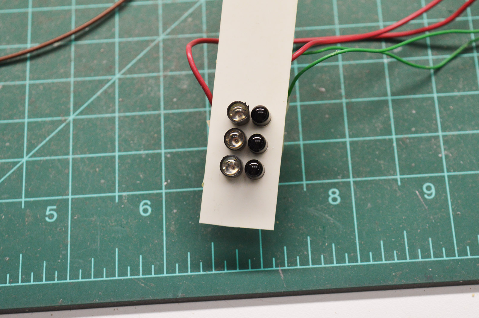
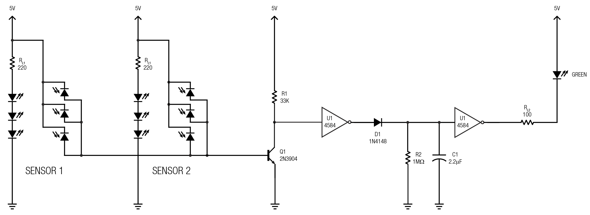
The rolling stock / sensor tests showed three sensor heights are needed to reliably pickup every car. Heights of 0.580″, 0.830″, and 1.120″ above the roadbed were the sweet spots. I fashioned a three head test sensor at these heights. Coincidentally, to obtain 6mA LED current with three LEDs in series required the original 220 ohm resistor I swapped out for 680 ohm earlier. The bottom IR pair are almost exclusively for flatcars including depressed center while the top pair detects tank cars well. The center pair is near car sill height and thus picks up all common cars (boxcars, hoppers, etc.). The three pairs are each actively detecting a car albeit to different degrees. It is the culmination of the three that dictates the output signal. The triple pair sensor initially returned detection of common cars at ~200mv to ~500mv depending on color. Dark voltage was well above 4v. Flatcars were the troublesome units pulling down to only 1.8v at best. Sometimes as high as 2.5v. Black tank cars were the other voltage outlier rarely dropping below 2v. To help with detecting flatcars and tank cars the voltage bias was adjusted downward by changing R1 from 22k to 33k. This brought flatcar/tank car detect voltages down into the 1v neighborhood. Increasing the value of R1 even further would have pulled the troublemakers down sub 1v but the tradeoff was a dark voltage too far below 4v. At 33k regular cars dropped all the way down to 100mv or less! The dark voltage with R1 at 33k is 3.9v. I’m calling those results close enough!
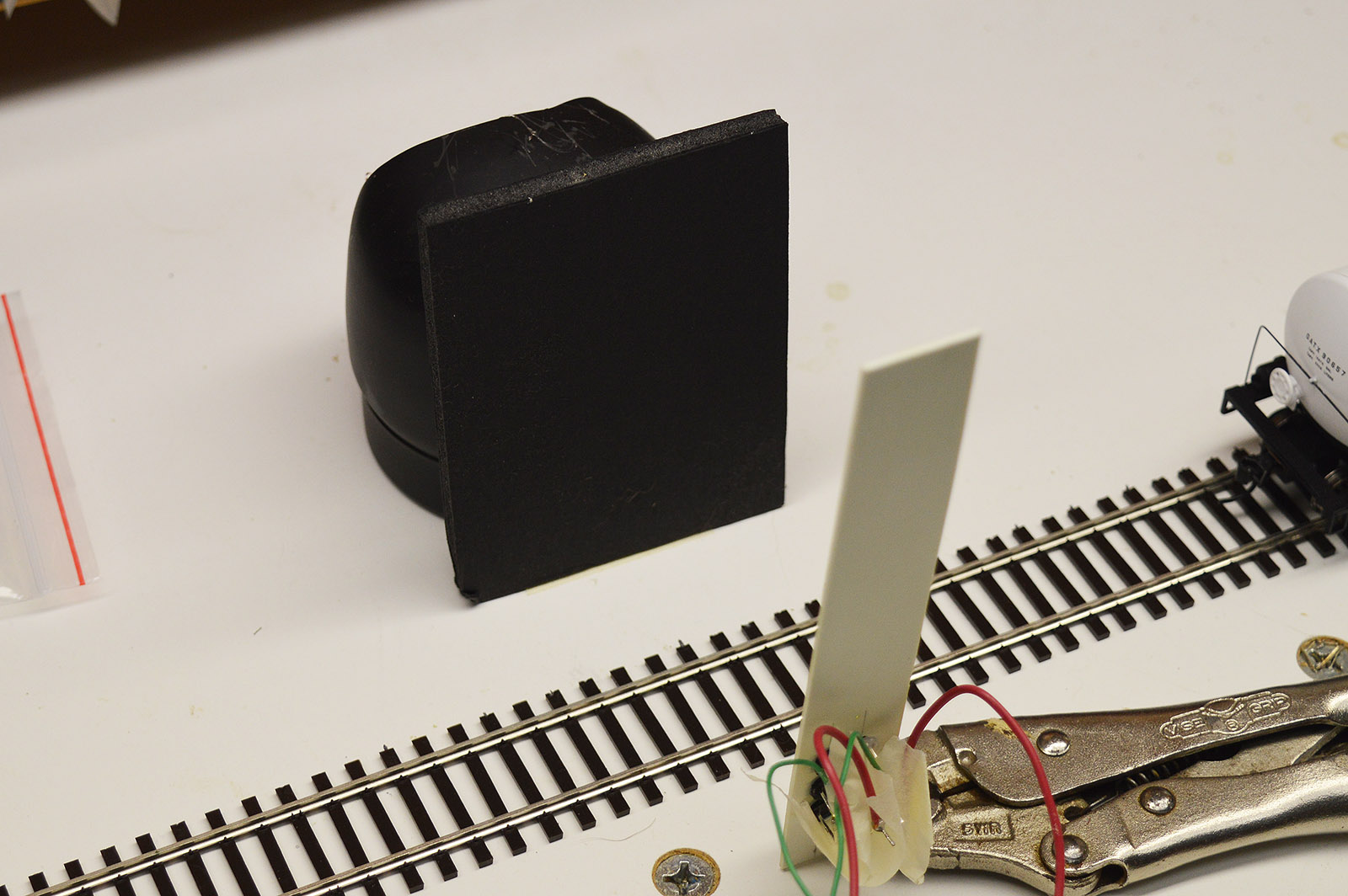
My backup plan for the problem of light bouncing everywhere and also to facilitate mass production with fixed component values (no fine tuning each unit individually), I added an IR absorber on the far side of the track. Discovered black gator board is a good IR absorber. Very little IR light is reflected back. These will be glued onto the outer radius of the helix if light bounce is a problem. I’m hoping the 6mA LED current will do the trick by itself but just in case.
The circuit optimized for a detect voltage of 1v or less regardless of car height, shape, or color and with a dark current of 3.9v now looks like this.
Blinking and flashing
Detecting a standing car is one thing, detecting moving cars is another. The gap between cars causes the green LED to blink as cars pass by. Even open boxcar doors or gaps between a flatcar load or opera windows in a centerbeam car can cause the LED to extinguish momentarily. Naturally, the slower the train is moving the more annoying this becomes. A pulse stretcher was needed to fix this issue.
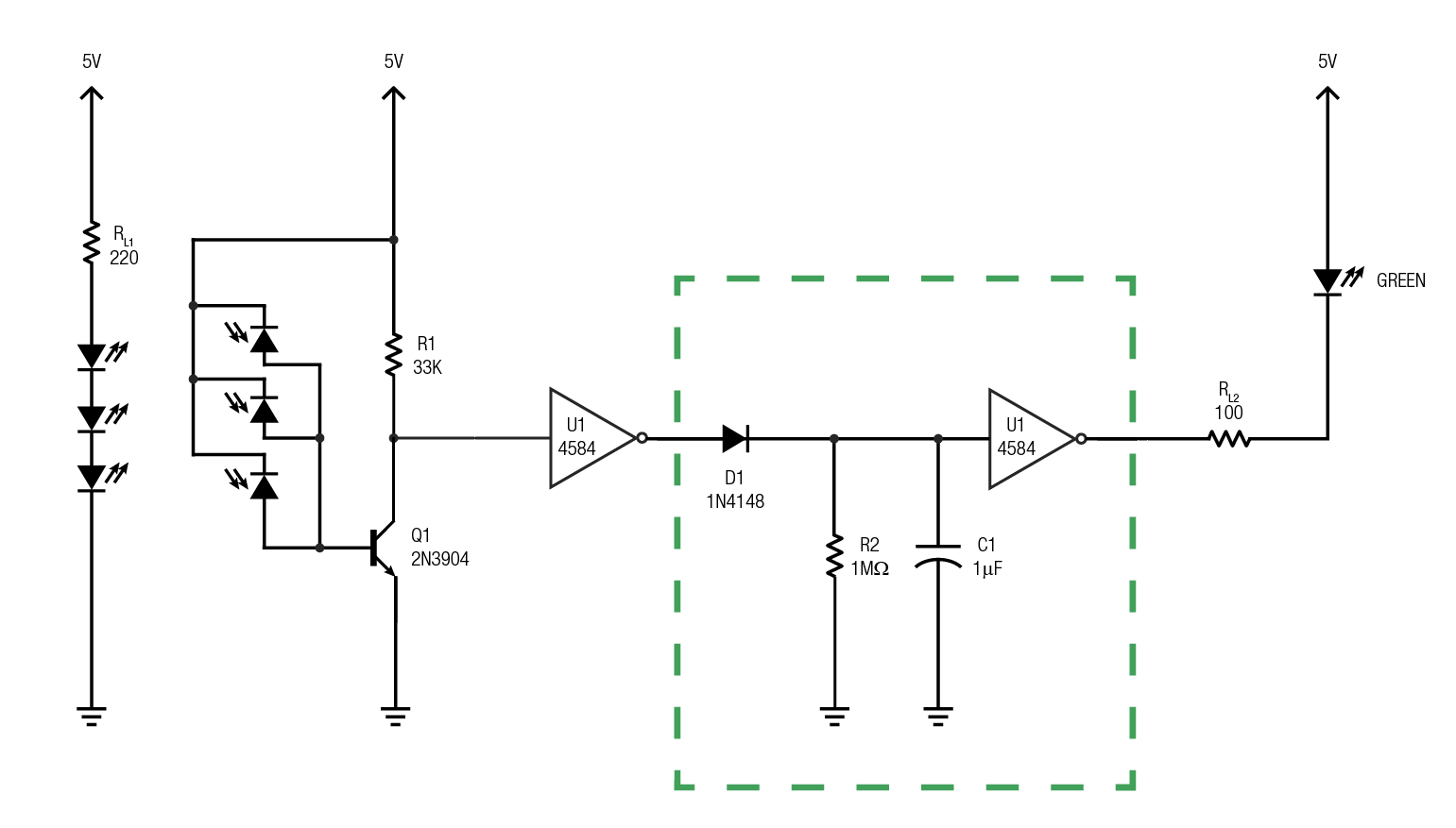
The dotted green box in the image below shows where a second gate and RC network was added to the output of the original gate. When the output of the first gate goes high (low on input/detect) the output of the second gate goes low (green LED on) while simultaneously capacitor C1 charges. When the first gate goes low (high on input/dark) C1 discharges slowly through resistor R2 holding the second gate high for a period of time until C1 discharges to below 2.1 volts. The discharge of C1 back through the output of the first gate is prevented by diode D1. Because C1 charges almost instantaneously but takes a while to discharge due to the large resistance of R2, the net effect on the output of gate two is a stretched pulse. Now any time a detect occurs, a pulse of at least 1 second duration is created at gate two output. A new pulse arriving before the prior pulse has expired will just extend the pulse further. Since it takes less than a second for the car gap to pass even at slow train speeds the LED doesn’t blink off between cars. Adding the second inverting gate reversed the LED operation so it is now wired to 5v instead of ground.
Long trains short trains, fast trains slow trains
My original plan was to hang a sensor on each helix upright. On the uprights only because they make a convenient mounting point. This would have given 12 sensors per loop for a grand total of 60 sensors.
There is a big flaw in that plan. Consider what would happen if a single locomotive were traversing the helix at a very low speed. The panel LED would come on and then go off before the locomotive reaches the next sensor. Watching the panel it would appear like the locomotive is appearing and disappearing in the helix. My knee jerk reaction was to extend the pulse stretcher out far enough, say 5 seconds, to allow the locomotive to make it to the next sensor. But that has an unintended consequence. What if the locomotive were moving really fast. It could cross multiple sensors before the first sensor timed out. On the panel it would look like the locomotive is a full helix loop long! Hmm, maybe time to get out the stopwatch and run a train back and forth.
Final conclusion – 60 sensors is not enough. There just isn’t a sweet spot between pulse too short and pulse too long because of the distance between sensors being much greater than the locomotive length. Doubling to 120 sensors, thus reducing the distance to roughly one and a half locomotive length, and fiddling with the pulse length does reasonably stay within the observed train timing. With 120 sensors and a pulse length of about 2 seconds the slow speed locomotive makes it to the next sensor just as the first sensor times out. At most, the panel LED will blink off for just a fraction of a second. The locomotive moving at high speed will appear as 2 to 3 panel LEDs in length. The stretch effect on the panel will only be noticeable with lone locomotives and trains one or two cars long so I can live with that. The alternative is a ton of sensors or a much more complicated circuit. Thankfully, I have enough IR pairs to make 120 sensors.
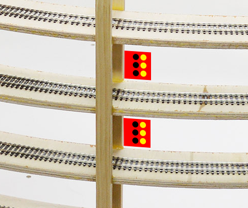
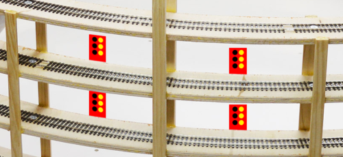
The auxiliary uprights are the obvious place to mount the additional sensors but I realized if I place all the sensors between the uprights they double as spill protection. Cars from a stringlined train won’t tumble to their destruction on the concrete floor if they fall from inside the helix. My new mounting positions:
Double sensors doesn’t mean double everything
120 sensors is a lot of sensors. While that quantity of sensors fixes the long short fast slow train problem, it is way too many LEDs on the fascia panel, too much wire, too many connectors, the list goes on. I was perfectly happy with 60 LEDs on the panel and, as luck would have it, my standard panel connectors have 64 pins.
I noticed earlier the dark voltage barely changed when I added the two additional photodiodes to the original circuit. Let’s try six! Works great. The dark voltage only dropped 0.2v from 3.9v to 3.7v. Given the actual helix location will be darker than my poster board covered test setup, I suspect the dark voltage will be closer to the ideal 4v. The six photodiodes in parallel means I can feed one circuit with two sensors. I don’t have to build 120 of everything.
The doubled up sensor circuit (with 2 sec pulse) now looks like this:
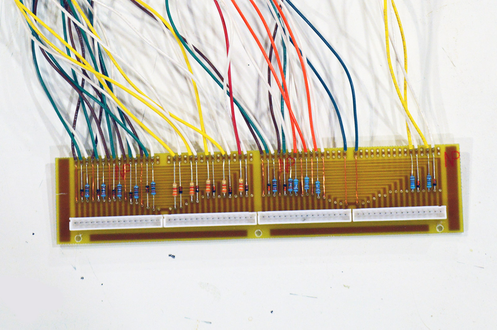
I may have to build 120 sensors but I don’t have to build 120 or even 60 circuit boards. I am going to condense 20 sensors (10 of the above circuit) onto a single circuit board. That will result in 6 boards, one mounted on every other upright and wired to its respective 10 sensors on its left and 10 sensors on its right. This makes better use of the 6 gate IC packages while simplifying fabrication and mounting.
Protection
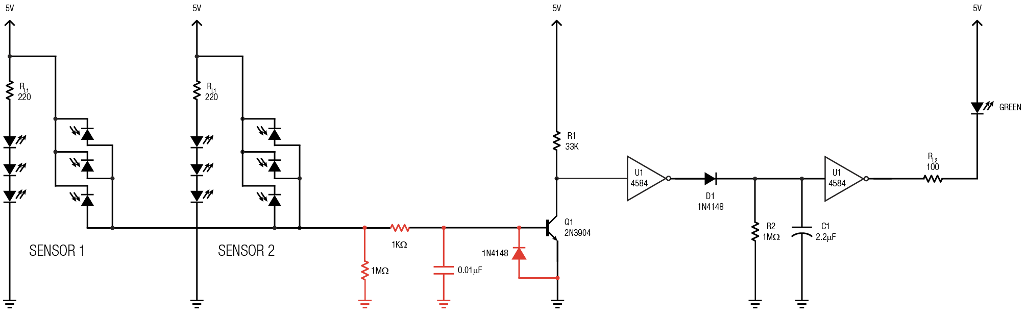
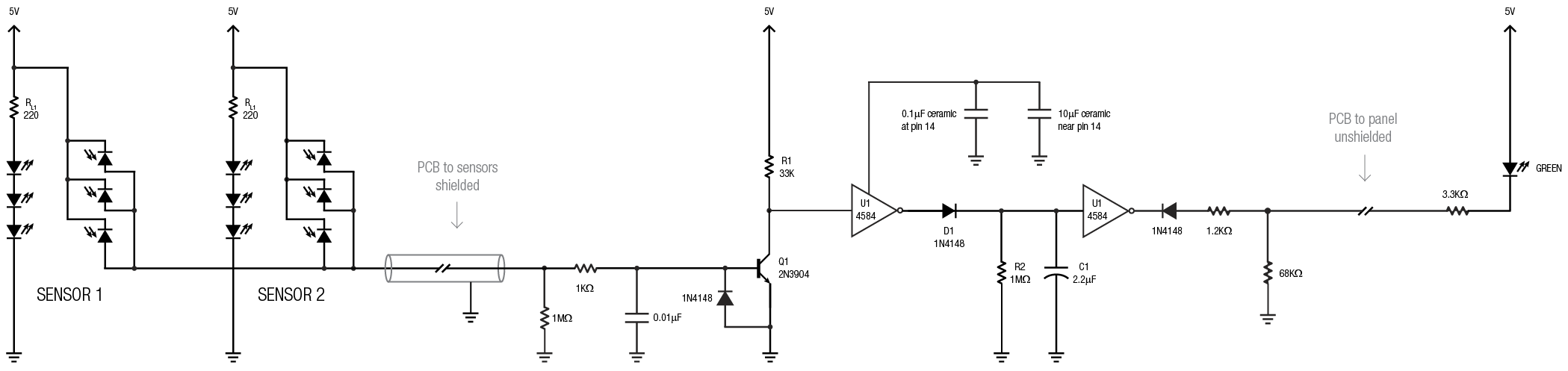
The offboard sensors require short interconnect wiring. The wiring has the potential to act as an antenna. That opens the door to electrical noise and potentially damaging voltage transients at the input of the circuit. The current through the photodiodes is only a microamp or two making the circuit especially sensitive to noise on the line. Using shielded cable goes a long way in preventing noise on the line but it doesn’t entirely protect from transient voltages. For assistance with circuit protection I turned to the helpful folks at eevblog.com forum. They suggested, in addition to using shielded cable, I should add the protection components shown in red below.
While we are on the subject of protection it is a good time to mention it is always good practice to decouple the ICs from the power supply. The garden variety way of doing this is shown in red below.

A final touch
It looks like I may have a ready-to-build helix detector on my hands. Time to add a “nice to have”. The LEDs on the fascia panel will be extinguished when no train is present in the helix. There is no way to distinguish between the helix being train free or the detection system isn’t working. Plus, the fascia panel won’t be ascetically pleasing with no LEDs lit. My final touch is to add a faint glow to all of the panel LEDs. It’s a fault indicator, makes the panel look nicer, and a train will show as a line of bright green dots moving along a helix shaped line of dim green dots.
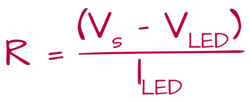
The helix fascia panel LEDs need to be the same brightness at 5v as all the other panels on the layout at 12v. The fascia panels on the LK&O use a 22k resistor on the green LEDs (3.2vf) resulting in a drive current of 0.4mA. Plugging the numbers into Ohm’s Law gives us a value of 4.5k ohms to achieve the same 0.4mA at 5v.
4.5k is not a standard resistor value. Normally, a 4.7k would be substituted. It is a good idea to have at least 1k of resistance on the output of a CMOS gate when the output line extends off the circuit board. I could place the 4.7k on the board and be done. My standard fascia panel connector boards have a place for a series resistor in the line. This means I have two places for the panel LED resistors. I can hit the ideal 4.5k value and maintain CMOS protection on the output. 1.2k on the board plus 3.3k on the panel equals 4.5k. Granted resistor tolerance means the 4.5k value is not guaranteed but it feels good to know I got as close as practical.
With the panel LED values calculated it was time to make them glow. By trial and err I settled on 68k of additional resistance (71.3k total) to make a nice glow. This gives a current of 0.03mA which is greater than a 10:1 reduction of the ON current of 0.4mA. Bright enough to see under layout lighting yet dim enough to provide high contrast to the LEDs normal ON brightness. The glow addition is shown in red.
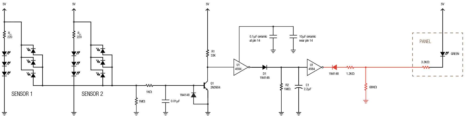
The series diode effectively removes a high output on the gate from being seen by the panel LED. The two possibilities become 1.2k to ground (gate output is low) or 68k to ground (gate output is high). Ta-da! Dim and bright panel indication.
It’s showtime!
Whew, that was a long winded post. The final basic circuit:
Replicate it ten times and you get one upright’s worth. Replicate that six times and you get one helix’s worth. 120 sensors, 60 circuits, 6 circuit boards, and a whole lot of wire. Call me crazy but I think this will be fun!
Let’s see if I can build it.

Hey Alan, greetings from Toronto, Ontario. Several weeks ago I was searching for poop on shelf/wall-mounted baseboard ideas for an N scale build I hope to start this Fall, 2021, and came across your intriguing blog. As I say, it was maybe 3 or 4 weeks ago, and it’s taken me that long to study each post and every comment, from Day 1 through to the present. I looked forward to absorbing several hours worth of browsing every evening, and always came away with a profound sense of admiration, wonder and amazement at all that you have gone through during more than a decade of model railroad construction.
Your odyssey has provided me with untold new knowledge, insight, enlightenment, entertainment and ambition, as well as an elevated dedication to thorough thought, contemplation, patience, and careful attention to detail, neatness and engineering throughout my upcoming build.
Just the fact that you waited YEARS before actually running a train across the entire upper level for the very first time speaks volumes about your thoughtful, step-wise and carefully considered approach to doing things right the first time, every time. Suffice to say that I am in awe at the myriad of skills, knowledge, innovation and technique that you have brought to this endeavour, and I anxiously look forward to your future instalments. I have deduced from your blog history that summer time sees your attention diverted elsewhere, but here’s hoping that you get back to modelling (and blogging) within the next month or two.
It’s an astounding accomplishment thusfar, and I’m sure your many followers are anxious for more. Best wishes going forward, from a new and dedicated fan!
Wow Dwight, I don’t know what to say other than I am flattered. Thank you.
Yes, model railroad activity slows greatly during the summer especially so this summer. Been real busy on outdoor stuff. Work on the railroad will resume soon. Summer is beginning to wind down.
The flattery is earned and deserved. For what it’s worth, here’s a little background to what your blog has done for me.
I had last modeled with N scale as a teenager back in the early 1970’s. University took precedence, then work, and family etc., but I had always hoped to resurrect the hobby someday.
I opted for early retirement at 53 years old, back in 2009 (quick math – I’m 65 at this writing). Over the next 10 years post-retirement, I built a pretty nice 4’ x 8’ dcc layout. High degree of realism, not at all “toy-like”, well constructed and reliable. It kept me occupied, and in the latter years, it proved to be hugely entertaining as four little grandkids made the scene. Two months ago, it felt like it was time for something different, so I completely dismantled everything.
Coincidentally, I decided that I needed to address a few preliminary prep steps before layout construction could re-commence … things like drywall the train room, pour some self-leveling concrete on the floor, reconfigure/rebuild the basement workbench, finish the ceiling with recessed lighting, etc. I also decided that I’d had it with stretching across a 4’ layout span, and that a bracket-mounted shelving approach would be better, perhaps constructed off-site in modules. I picked up a big roll of butcher paper, thinking I’ll draft out the layout, in 1:1 scale, on the floor, as a template. Sounding familiar, right?
And THAT’S when I found your LK&O adventure, which has confirmed not only the viability and practicality of all that I was contemplating, but SO much more. Like, using Tortoises with one-touch control, and good grade plywood and Strong-Ties for structural fabrication, and cool techniques for neat, tidy, professional-looking wiring and cable management. Oh, and “etch your own PC boards”! That will REALLY push me out of my comfort zone, but, hey, why not?
Anyway, it’s clear that I’m pumped and inspired, and I have you to thank for it. However, space constraints mean that it won’t be anywhere near as large as what you’re working on. I hope to make a start in September or October. Looking forward to keeping in touch.
Happy that you found inspiration. Keep me posted on your progress.