The entire line from the tunnel exit at Mettiki mine east to Kitzmiller is one long, continuous ~2% downgrade. A little less grade on the curves, a little more grade on the tangents.
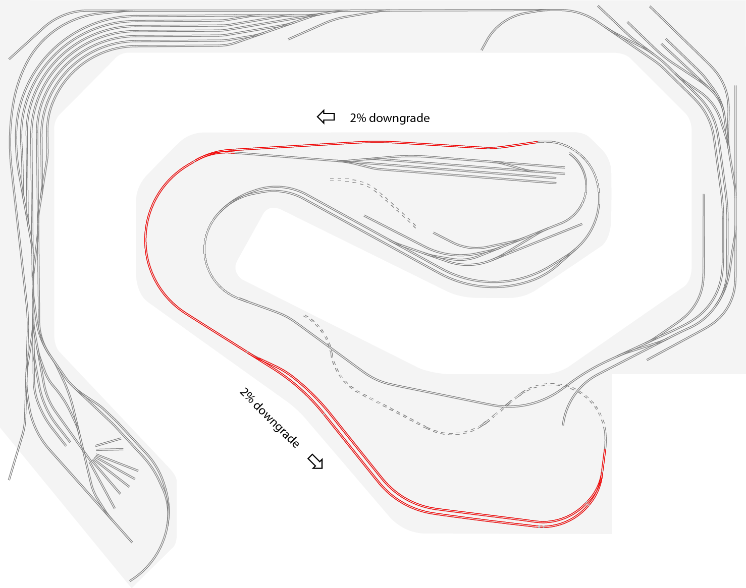
The grade presents a problem when trying to leave a cut of cars west of the mine or anywhere on the Kitzmiller siding. The cars roll away! Here is my old school way of fixing that problem – a pin between the rails.

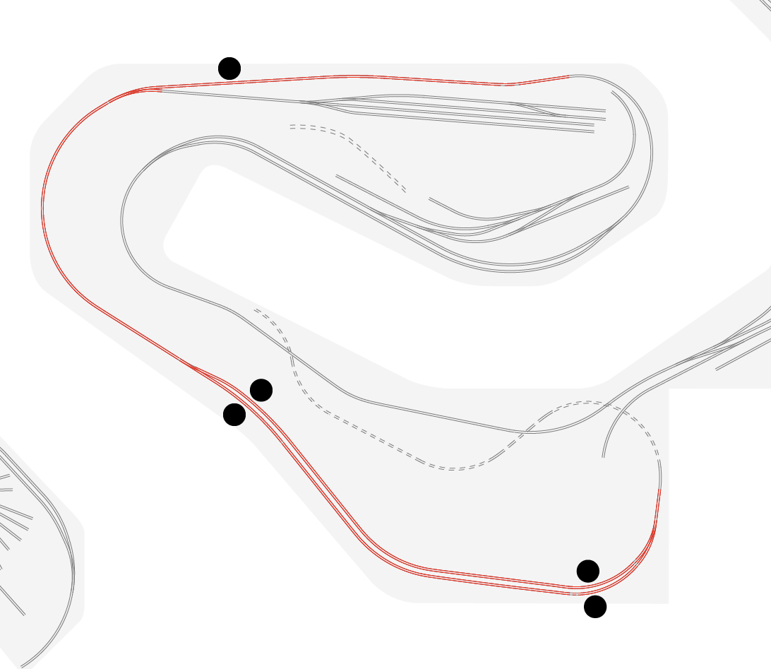
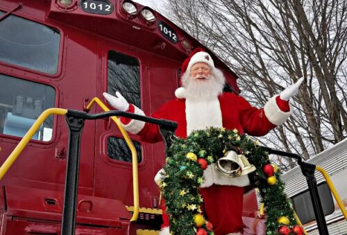
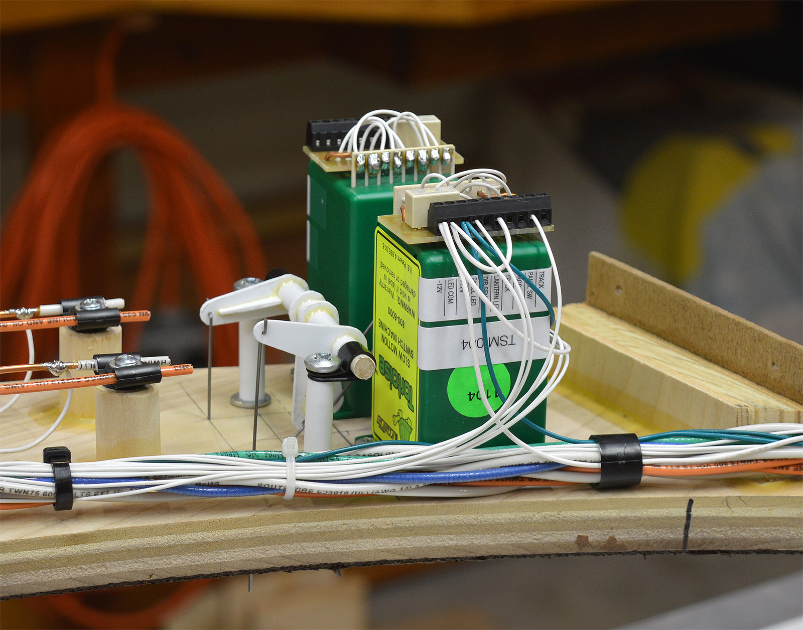
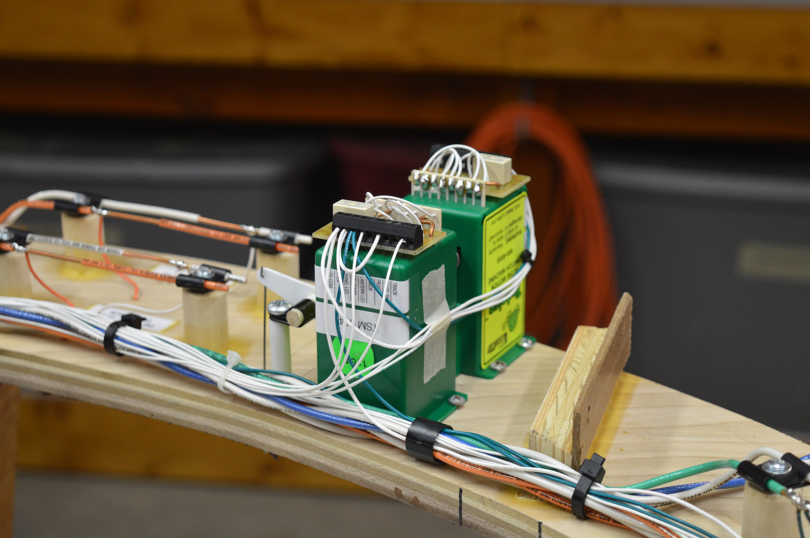
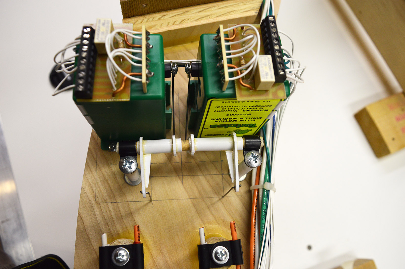
I elected to use Tortoise machines instead of servos because the Tortoise retain their position when the layout is powered down (or up). There are now five newly installed brake pins on the layout.
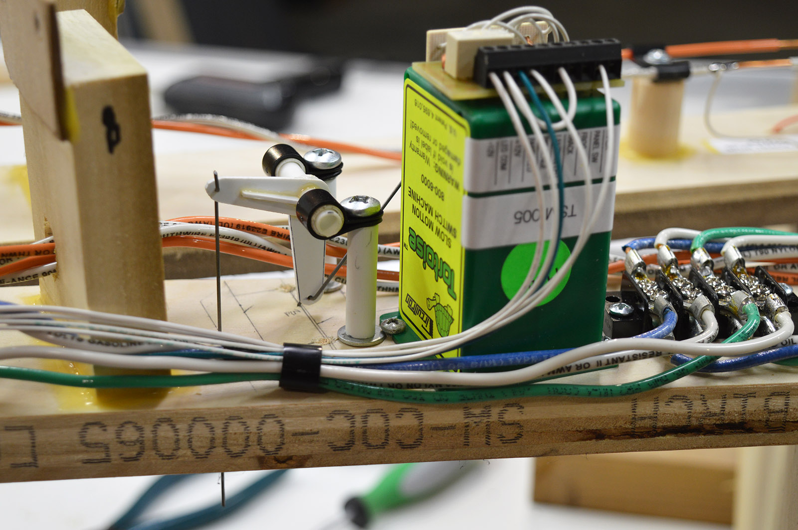
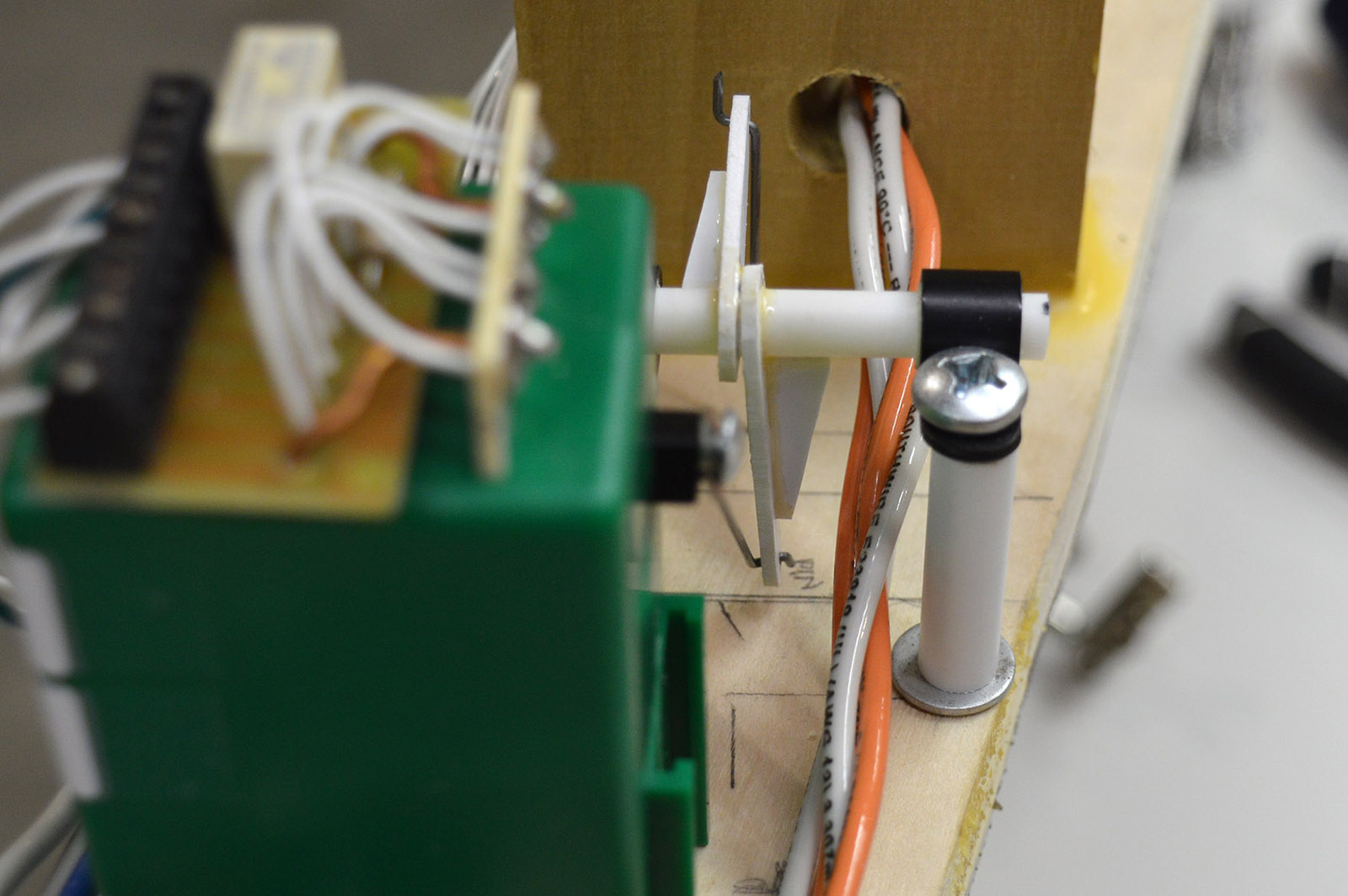
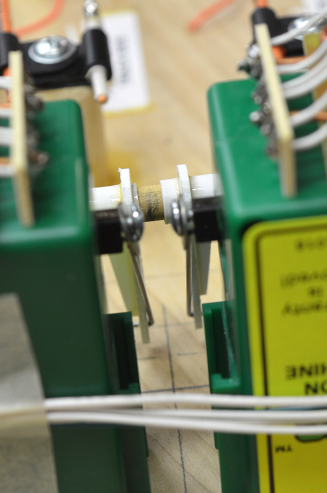
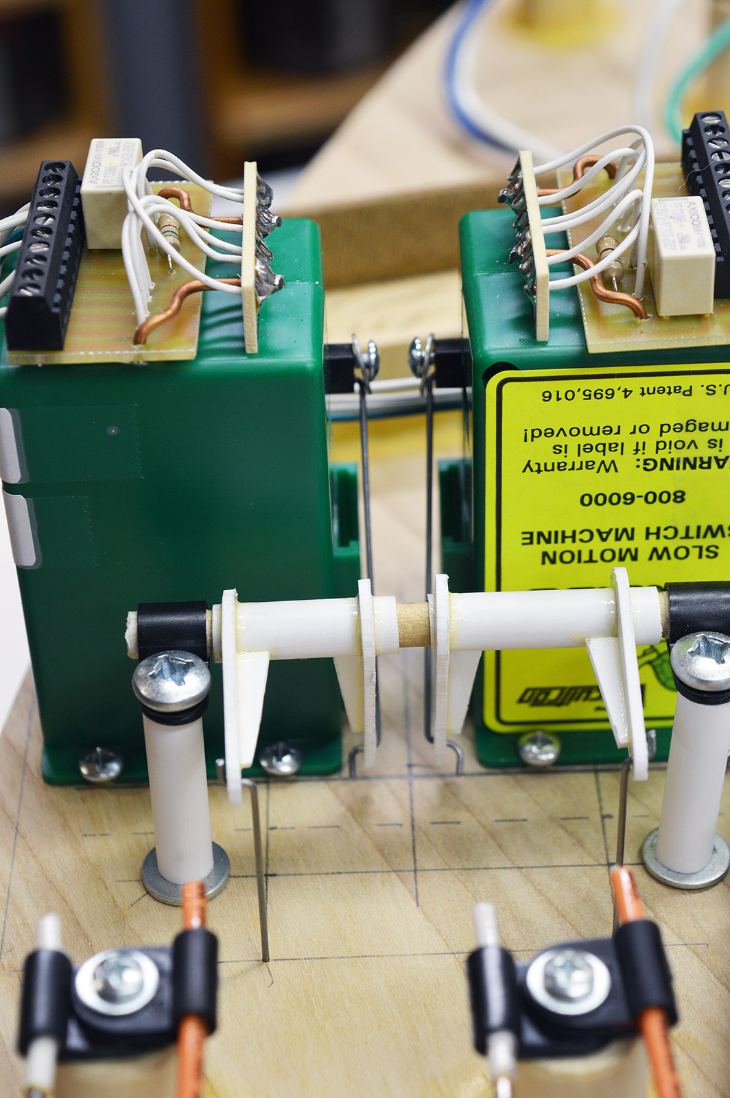
The pins are 0.039″ music wire going through 0.045″ holes in the sub-roadbed, cork, and tie. The lever assemblies are 0.060″ and 0.040″ styrene, shafts and bearings are 0.250″ and 0.312″ tube, screws are #12×2″ with 1-1/4″ risers resting on 1/4″ washers. I used a 36″ wheel axle centerline (plus a pinch) as the raised pin height.

The mechanics of raising and lowering the pin is just a simple pair of levers on a shaft. What was not so simple is the lever length ratio. Turned out to be quite a geometry exercise for me.
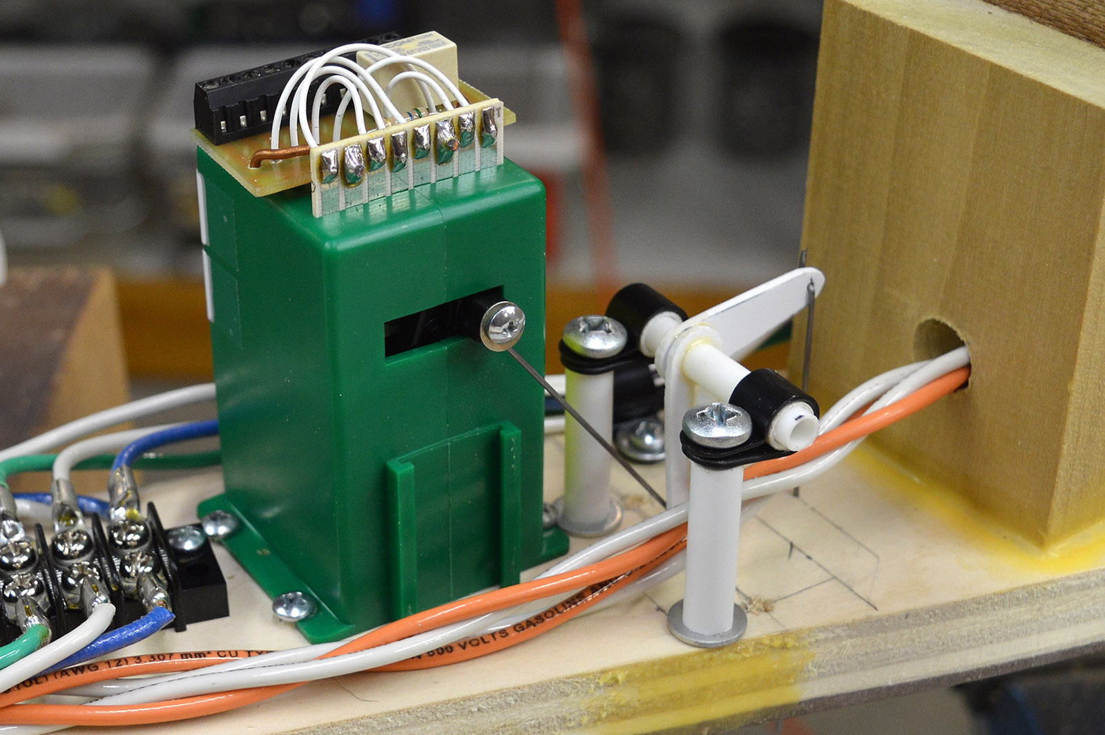
A Tortoise machine has a throw of 0.550″ (1/2″ nom.) while the required raised pin height is 0.375″. Simple enough, just make the levers in the correct ratio. Not so fast there. The physical dimensions and positioning of the Tortoises dictated the angle at which the Tortoise linkage connected to its respective lever which in turn changed the lever’s degree of movement relative to the Tortoise arm. Available space under the sub-roadbed did not allow me the luxury of using 90 degree lever/linkage arrangements. Working through the rod lengths and sweep angles gave me newfound respect for the designers of steam locomotive valve gear!
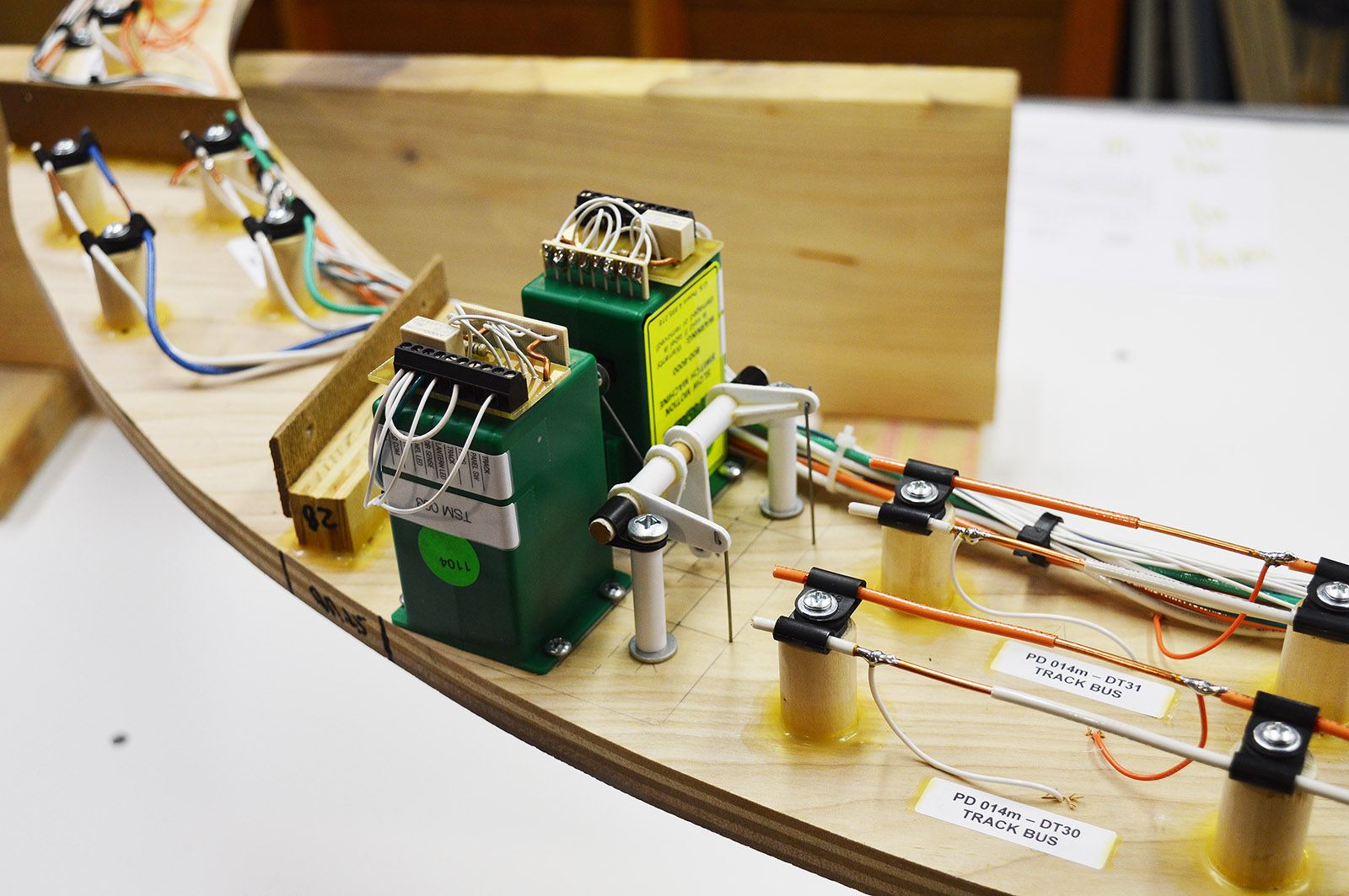
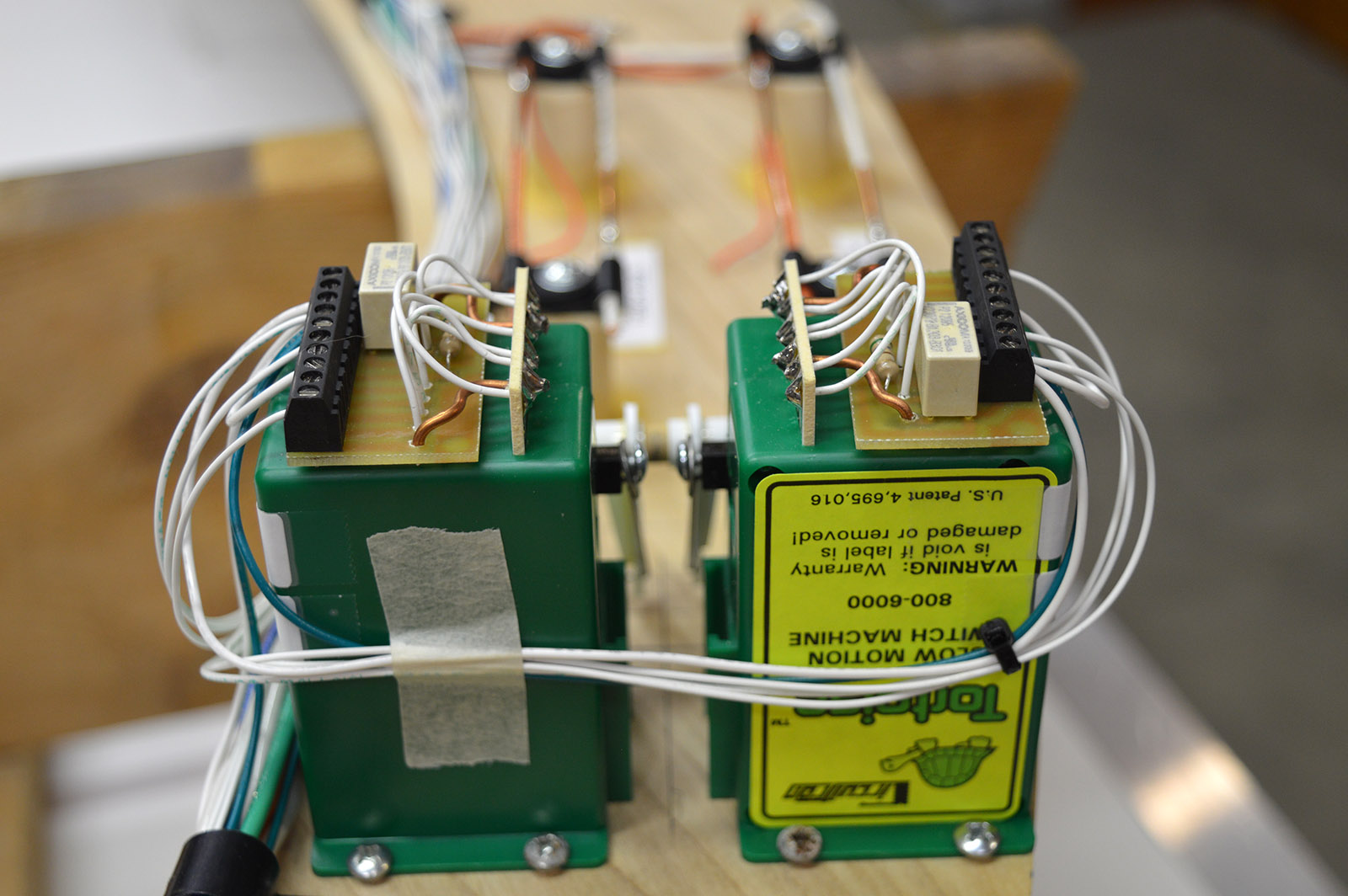
On the east end of Kitzmiller siding I put both lever assemblies on a common shaft.

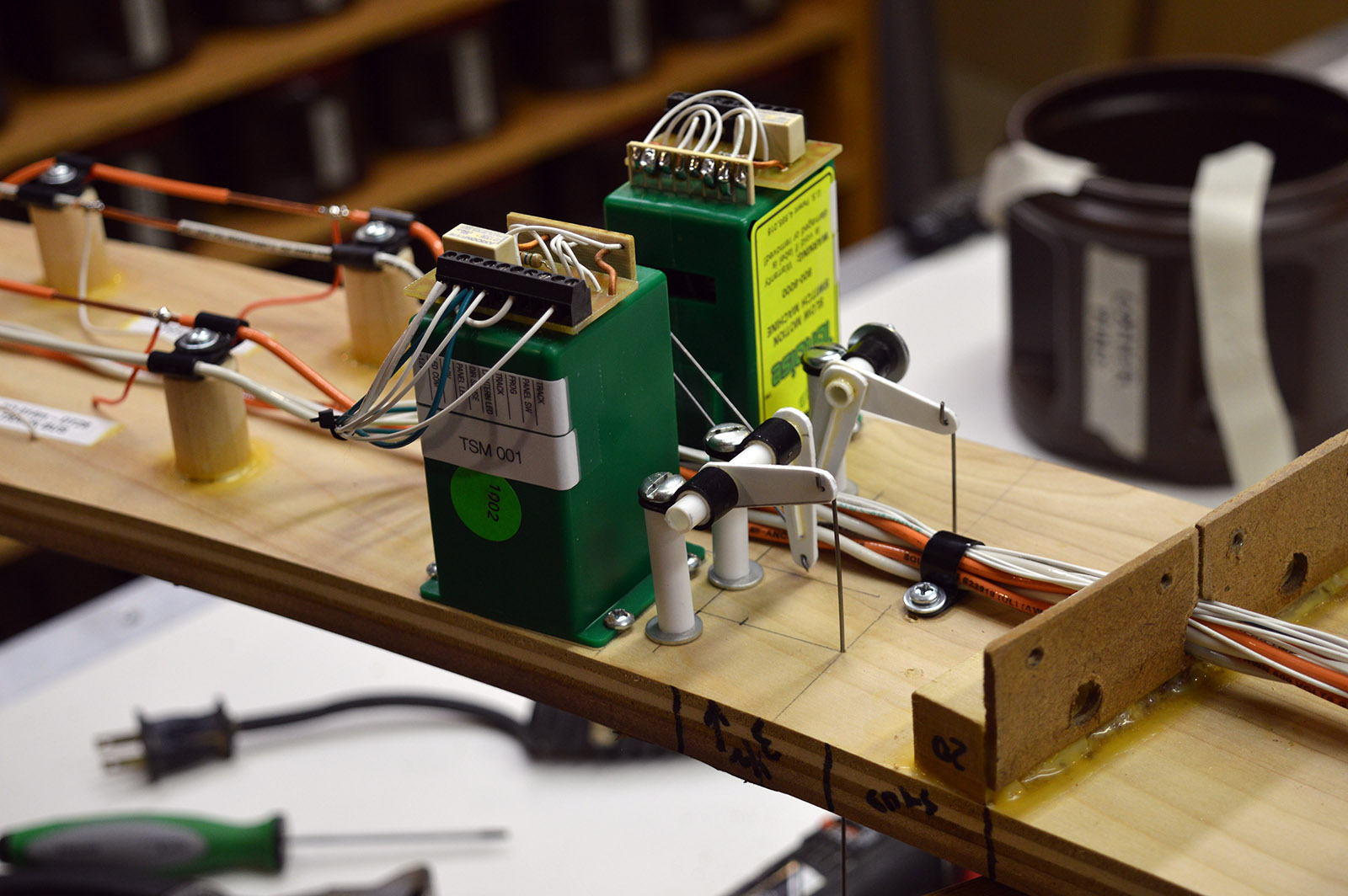
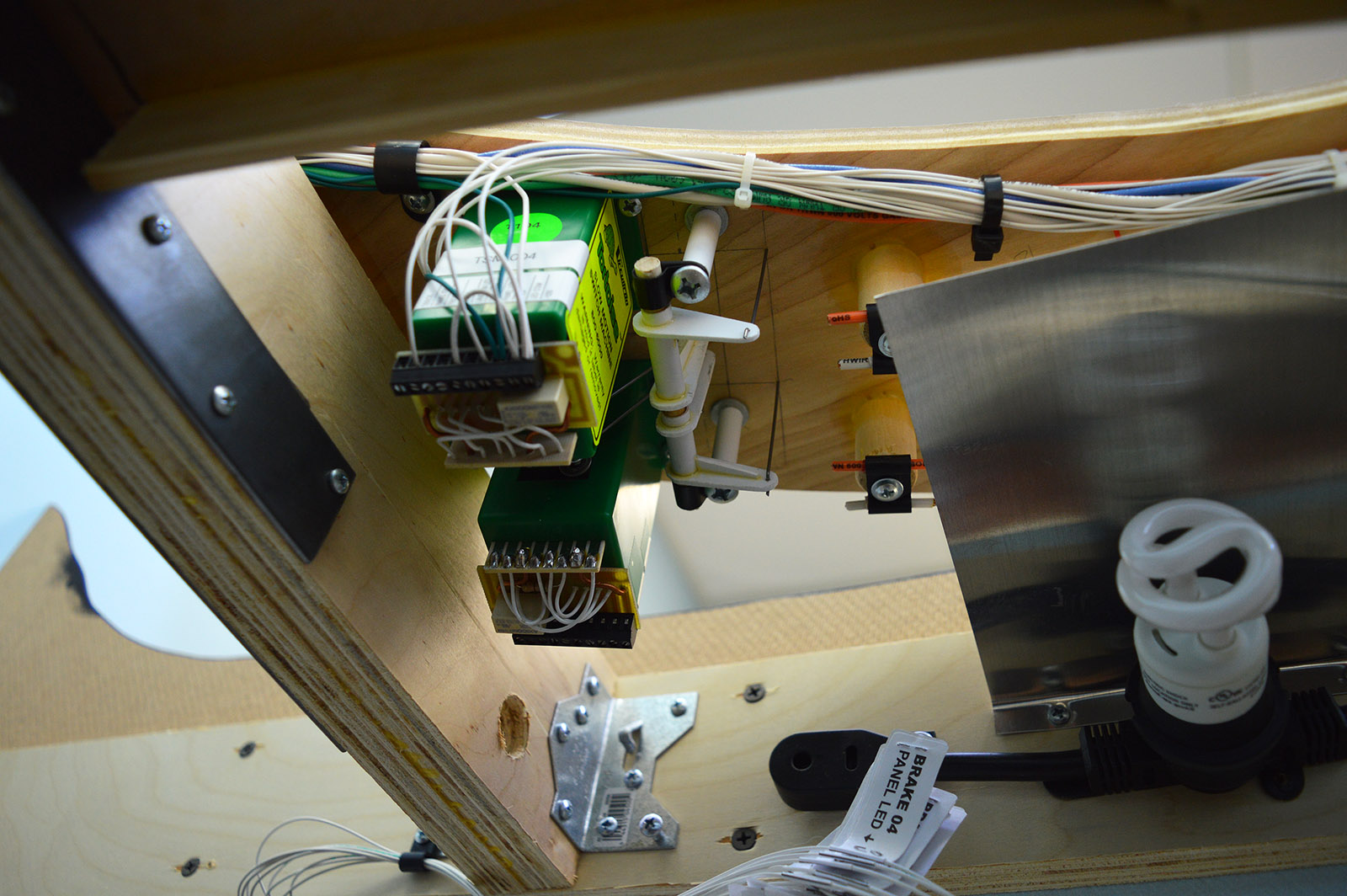
The west end of Kitzmiller siding uses individual shafts.

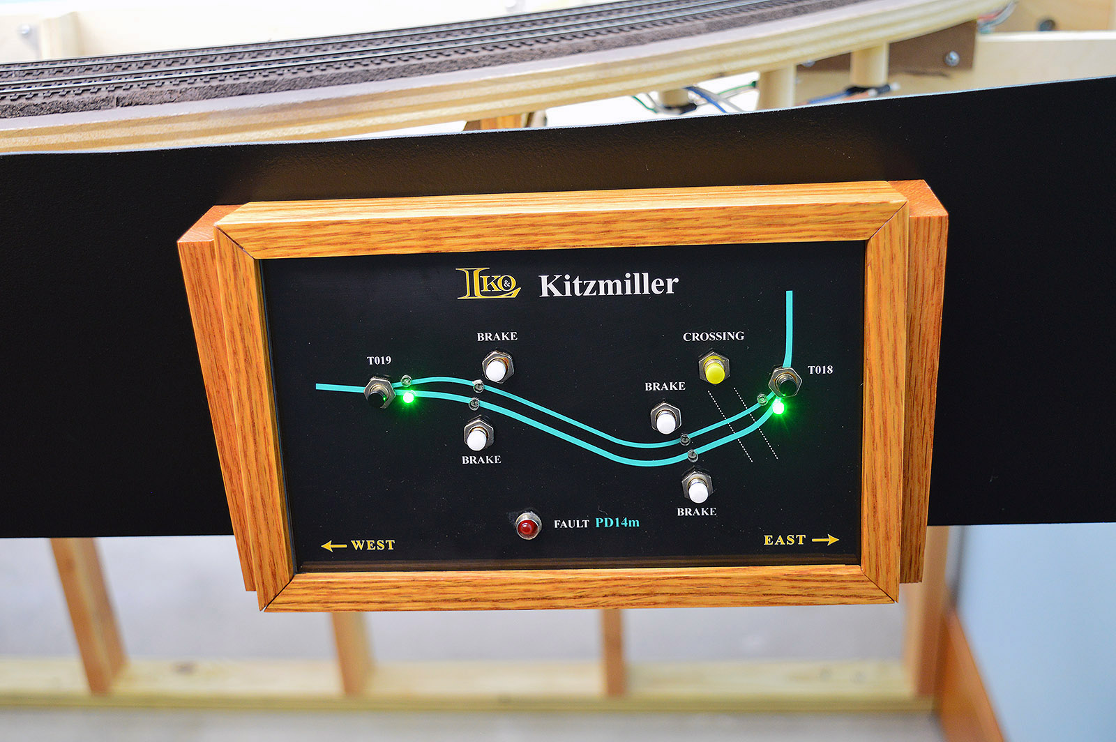
The Tortoises act and are wired the same as the turnout machines except with no track/frog connections. They are controlled by brake buttons on the control panels.
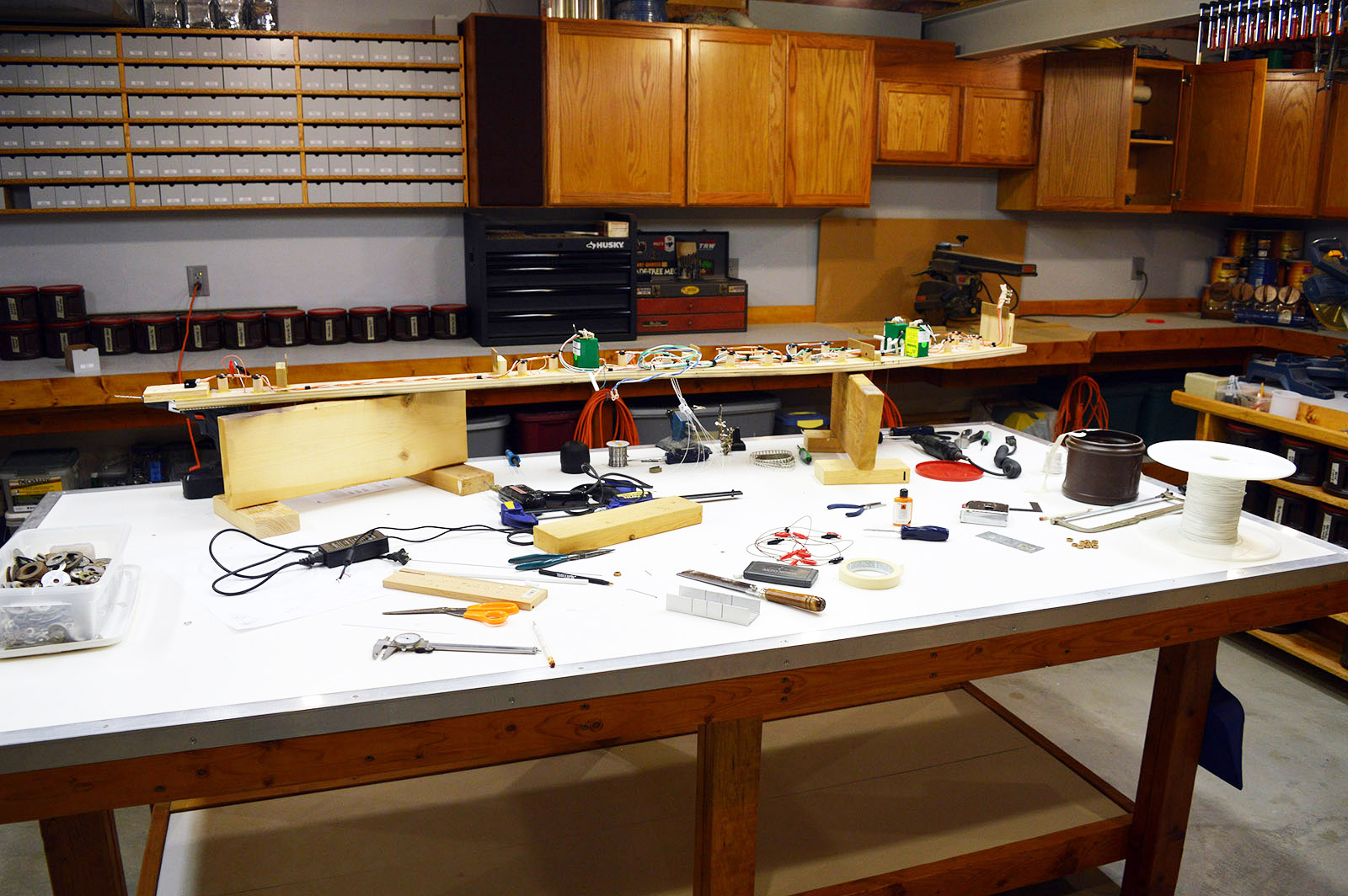
The removable track module design once again paid huge dividends. It was enjoyable to make, mount, and wire the mechanisms with the module upside down on the workbench. I can’t imagine how difficult it would have been to do the same work while laying under the layout working overhead.
I’ll make a little movie showing the brakes in action but first I want to add a feature I think will be really cool. That will come after the holidays. So, for now I will leave you with a gallery of random photos.
Wishing you Merry Christmas
and a Happy New Year!


Alan, that’s a great idea and a well thought out system. There are three areas that I could use such a system. Thanks for the info.
Alan, this looks like it will work great…..woe to the crew who doesn’t “release” the hand brake before leaving;-)
The operations aspect of this to me wonders about the lack of a hand brake for trains working the Mettiki Mine on a westbound move….or do all the locals work in a eastbound move??
Westbound moves working the mine use Kitzmiller siding for runaround.
Drop empties at siding.
Pull loads onto main.
Shove empties to mine.
Grab loads and leave.
As they say in Boston, “yoah wicked smaaaat”! that is very clever on multiple levels! Thanks for sharing! Merry Christmas!
A 3D printed wheel on the fascia to simulate the winding on & off of the break wheel would be a really cool feature…
I’m sure the extreme engineering mind of yours could create something that would work!
Excellent solution Alan, always look forward to your updates to see what you’ve come up with. Jas.
Jas, the proto-ops crowd would love that idea. Since some cars in my railroad time frame still had roof walks, the brake wheel could be on the upper fascia with a step ladder one must climb to reach it. 🙂 🙂 🙂
Hi Alan sorry I had not been able to comment on your post need to say keep the Great. I am definitely enjoying everything and this will definitely help all model railroaders out again I want to let you know sorry for not been able to comment on your post I have been really busy at work
That’s a cool system! No way I’d be able to figure that out mathematically. BTW, neat wiring