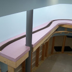
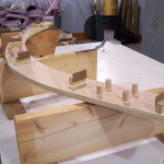
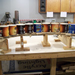
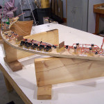
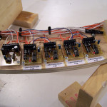
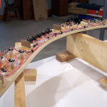
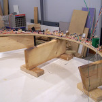
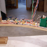
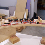
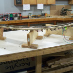
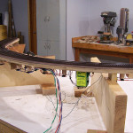
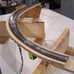
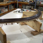
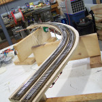
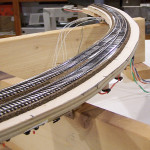
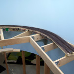
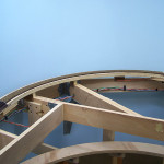
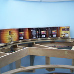
Modules #7 & #8 and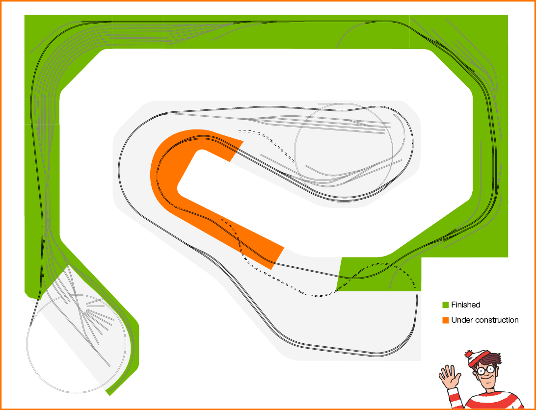 connector #7 are finished. This is the stretch of mainline that serves as a scenery transition between Ohio and Michigan as the rail line leaves Akron OH and heads toward Lapeer MI. Imagine tree covered rolling hills with the right-of-way passing through shallow cuts and over short fills with the occasional culvert or small bridge.
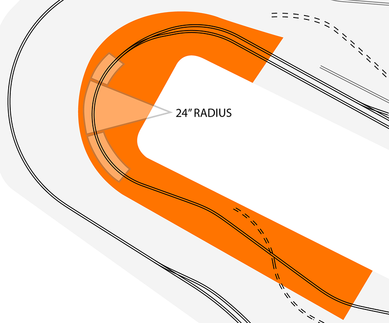
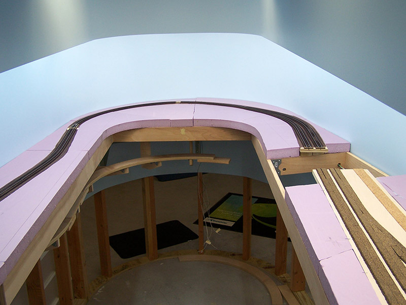
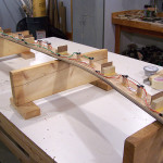
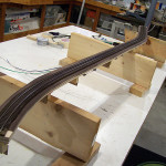
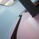
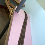
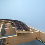
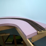
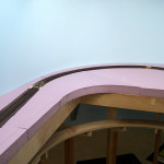
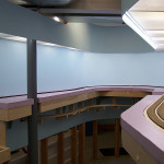
This is also the smallest radius curve on the main. It is 24″ at its tightest point but only for a short length. There are easements in and out to help mitigate the small radius. A relatively deep cut will block much of the train from view just as it goes through the sharpest point in the curve. Although right now with only flat pink foam for landscape the curve looks a bit wonky.
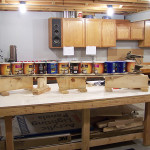
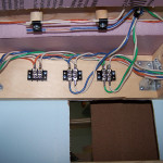
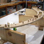
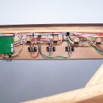
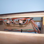
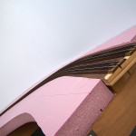
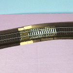
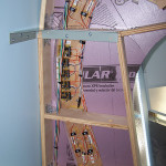
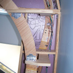
Otherwise, module building just like the ones before them. How about a few pics:

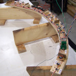
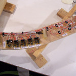
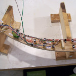
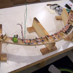


Coming along nicely Alan, seeing you mentioned the 24″R what is your longest loco & rolling stock? Jas.
SD70M’s but only for odd occasions. They are way out of my era. My roster is currently all 4 axle except for a single SD-35. Rolling stock is 60′ or less. Majority are 40’s and 50’s.
Not worried about the radius operationally. More a cosmetic thing than anything else. Helps that it is viewed from the inside instead of the outside.
I enjoy following your progress, Alan. I’m interested in how you put down your easements. Did you build the easements into the plan with your CAD program or did you build them on the benchwork with your calibrated eyeball?
I am using AnyRail5 on my plan and you can have the program construct an easement for you, as I am sure most model railroad CAD programs can. The track in your photos has a nice flow to it and I am curious how the flex track and commercial turnouts conform to a plan, and if the plan worked well as-is or if you have had to make adjustments on the fly on the benchwork.
Jeff
Jeff,
The easements were done in XTrkCAD. XTrkCAD’s dimensional representation of Walthers 83 turnouts is extremely accurate. The plan was printed 1:1, positioned on the sub-roadbed, and the centerline traced. Split Midwest cork roadbed was laid following the traced centerline. Track was then laid keeping centered on the roadbed. In areas where sheet cork was used, the printed plan was placed after the cork and then the centerlines traced. No track position adjustments were necessary during track laying. Tracing lines from the XTrkCAD print were followed as accurately as my eyes permitted.