As happens every year, the arrival of summer brings to a halt work on the railroad. This year was no different. It is late fall now and that means time to get back to working on the railroad.
Picking up where I left off, construction of the south helix panel commenced. The standard building method for my control panels was documented in detail back in 2016 so I’ll skip the redundancy and post only the parts unique to this panel.
[EDIT] Sorry, when I originally wrote this post I forgot to mention a key change. I decided to use blue instead of green LEDs on the panel. This necessitated a slightly higher LED current to get the brightness level right so I removed the panel connector board resistors from the circuit. It is for this reason you see jumpers instead of resistors on the connector board in the panel build below.

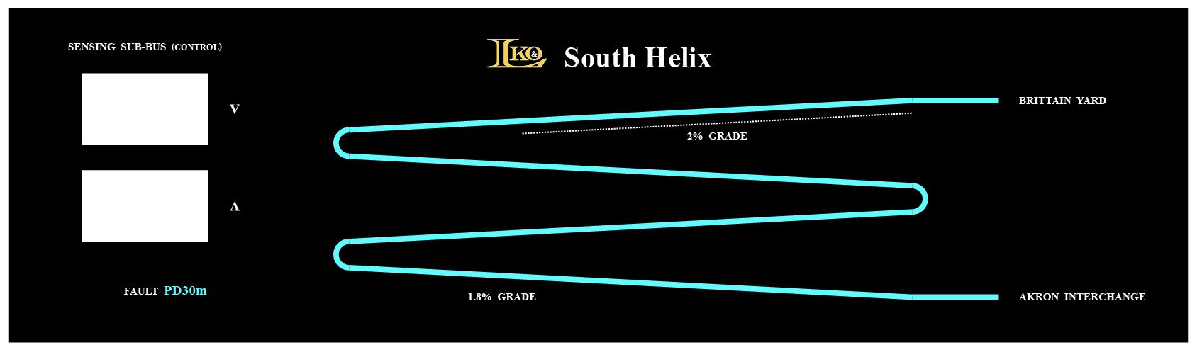
First up was the panel artwork. Another black ink cartridge gave its all for the cause!
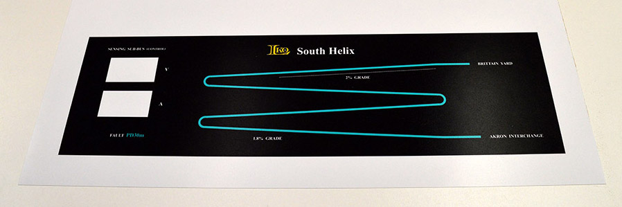
If you followed the helix build you may see something odd in the artwork. The helix has 4-7/8 loops (let’s call that 5) but the art shows 4 loops. The reason I did this was to make the entrance and exit appear on the same side of the panel which mimics the physical arrangement on the layout. A tradeoff for illustrating vertical as horizontal.
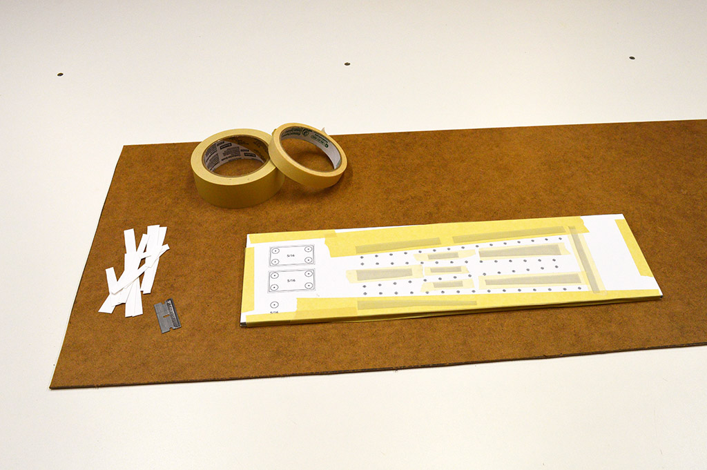
The usual stack of clear acrylic, inkjet print, styrene spacer, and fiberglass backing was assembled. Unwanted movement of the paper drilling template during bit withdraw was one of the issues I incurred on earlier panels. It caused some holes to be ever so slightly out of place. The helix panel with its straight lines of LEDs demands the holes be on target as it will be blatantly obvious if they are not. So, this time around I printed the template on heavy photo paper and added many more tape cutouts than in the past. The cutouts were also positioned closer to the holes.
To further increase my drilling accuracy, I mounted a pair of 75W halogen spot lights above the drill press pointed at the work piece. This made it insanely bright for drilling. The camera didn’t like taking a picture of the setup because it was so bright but my tired eyes appreciated it very much.
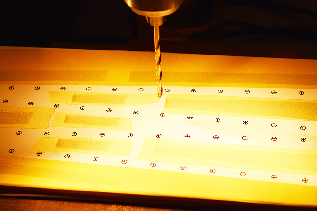
The combination of thick paper, oodles of tape, and thousands of lumens did the trick. The drilling results are much better than panels of the past.

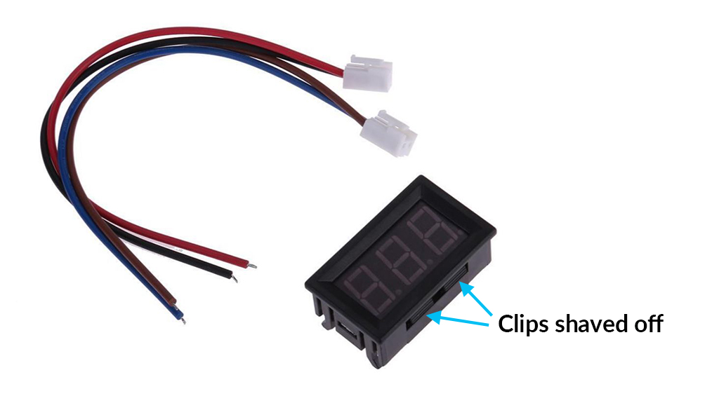
This panel has a voltmeter and an ammeter to monitor the status of the helix sensing power bus. The meter holes were cut with a jig saw. Perfect accuracy wasn’t needed due to the meter bezel extending beyond the cutout but I did deliberately make the meters a really snug fit. The meters have clips molded into their cases designed for securing into a thin panel. My panel is much too thick for the clips so I shaved them off and am relying on friction to hold the meters in place. The tight fit did make the meters challenging to insert but now that they are in place they aren’t going anywhere.
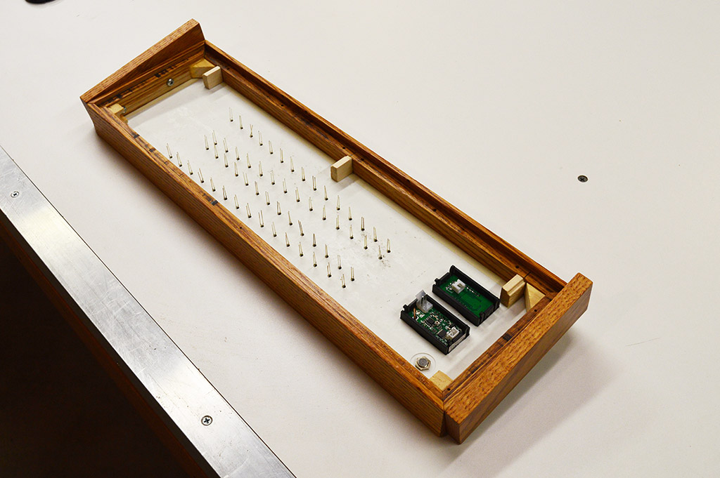
A picture of the assembled panel with meters, LEDs, and fault indicator installed ready to be wired.
The wiring color codes inside my control panels mean nothing. I use whatever wire color I have the most of. For some reason I have several rolls of yellow hookup wire so yellow it is on this panel. A single bare copper wire follows the line of LEDs connecting their anodes (+) together and to the positive rail. Each LED then received a yellow wire for its cathode (-) connection. Cardboard separators were placed for insurance against accidental shorting. The separators are glued in place with E6000.
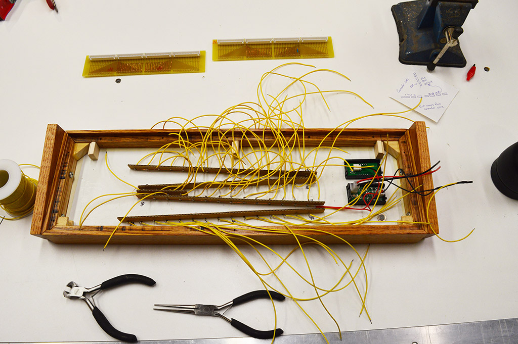
Next came the connector boards. Tedious work but eventually every yellow wire found its home. Fastening down the connector boards was the final step before bench testing the panel.
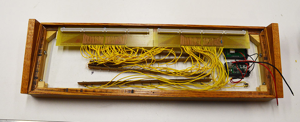
I would be lying if I said the panel tested perfectly. It seems along the way I crossed the wires for LED 51 and 52. A little rework fixed the problem and the project buttoned up with the back panel installed. Note the connectors are at the top of this panel instead of the bottom as on past panels. That’s because this is an overhead panel that mounts on the lighting valence and is tilted downward when installed. The red and black wires coming out separately are for the ammeter connection. The 5 volt power bus of the helix sensing is 3 amp and the maximum current for the style XH connector board is 2 amps.
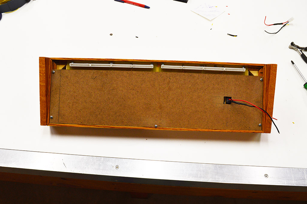
The finished panel ready for mounting. Ahh, it’s good to be working on the railroad again.

Happy Thanksgiving everyone!

Looks good. I’ll be following, as I have some panel construction in my future. Thanks for posting.
Lou
Hey Alan, it’s great to see you back at it. Your meticulous attention to detail and superior workmanship continues to inspire me. And not just with respect to model railroading … so many times, in so many other aspects of my day-to-day activities, I think to myself “what/how would Alan do this” (especially when there is a temptation to exploit a shortcut !).
Looking forward to subsequent posts.
Thanks guys. Quite the compliment there Dwight. I prefer to think “what would Spock do?” 🙂