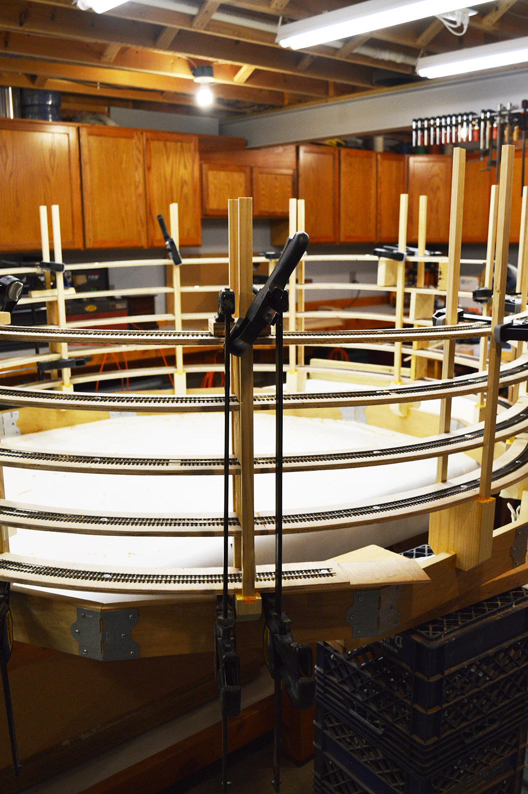
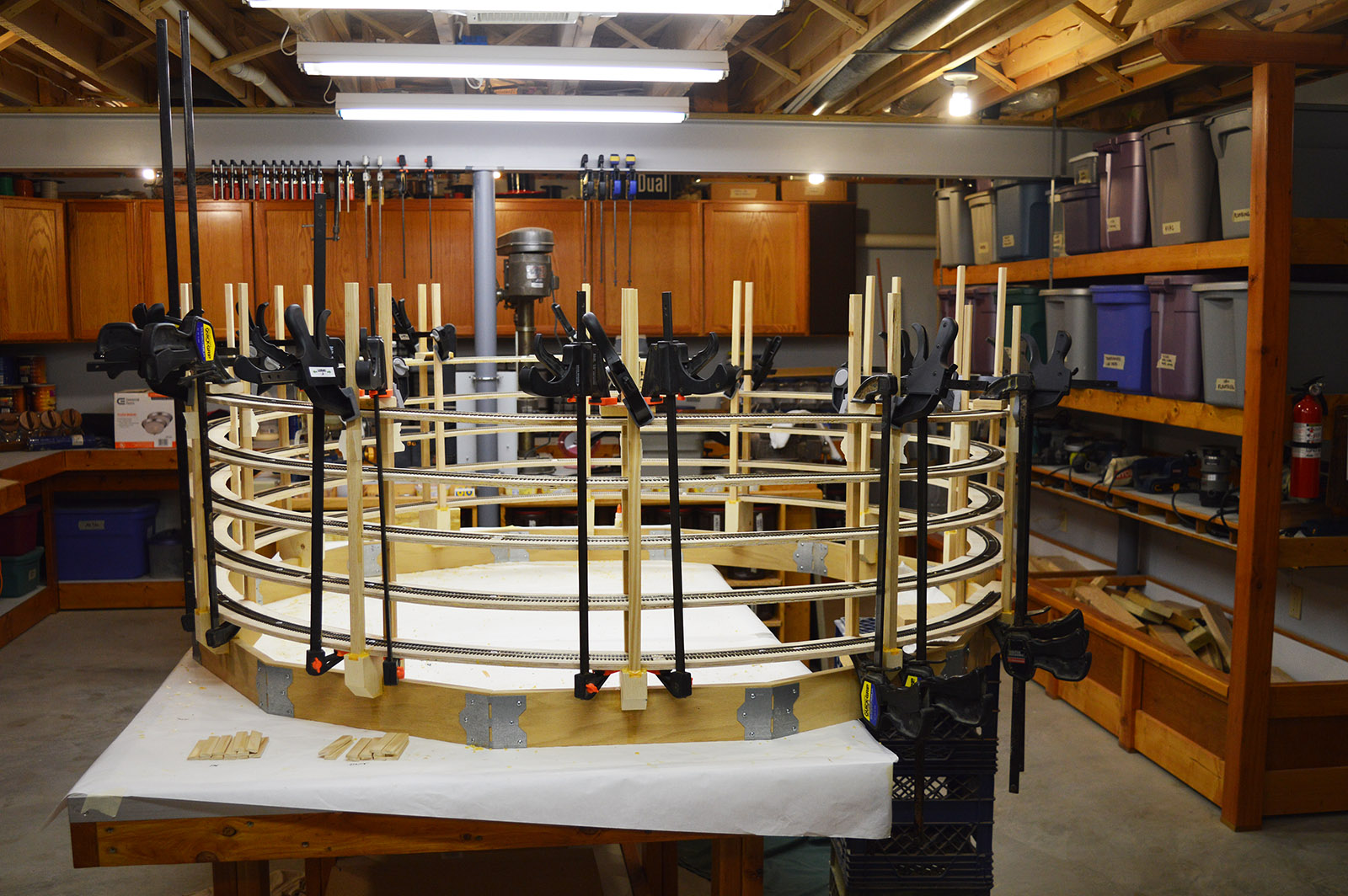
How about that, I’ve constructed my first ever helix. At least the wood and track part of it anyway.
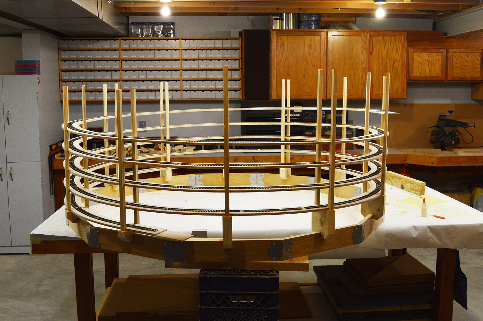
I believe I have discovered the absolute slowest method possible for building a helix. Laminating the roadbed sections together stretched out over many, many days. Glue, clamp, wait 24 hours, repeat. Well, installing the uprights did not go any faster. The instructions on the glue bottle say not to stress the joint for 24 hours. Since glue is all that holds the helix together I decided to abide by their recommendation all the way through the build.
While positioning and gluing the roadbed sections it was vital the assembly was not only the same diameter but also was straight up and down i.e. each loop had to be exactly above the loop below it. The screen trim spacers are only 1/4″ thick so it wouldn’t take much error to throw them all out of whack. I used a framing square referenced to the workbench surface as my guide. That sounds easier to do than it actually was. As the helix grew taller it also became more wobbly. A whole lot of clamping was going on to keep the monster aligned.
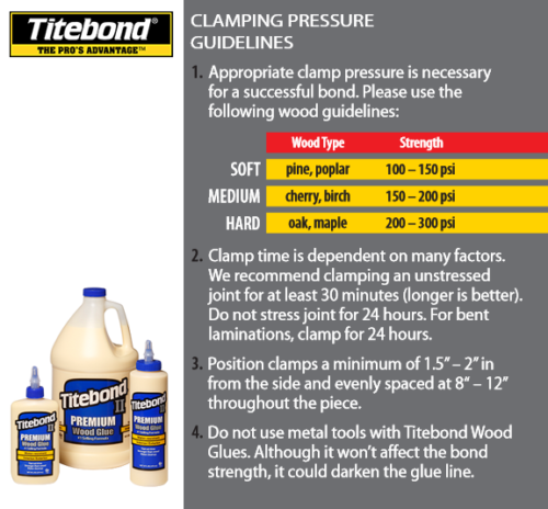
The moment of truth came when it was time to install the uprights. When the menagerie of clamps were removed I was relived to see the loops barely moved. But they did move a touch. To remove that last bit of misalignment, I clamped 2x4s vertically at 90 degrees around the helix. That did the trick. Loops were straight up and down.
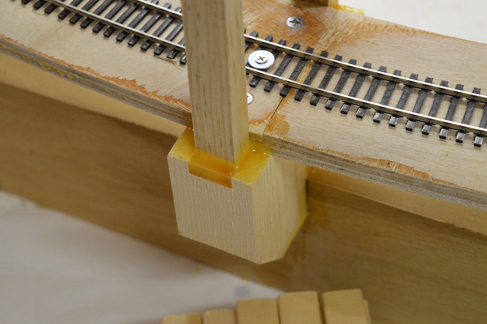
I cut 24) 23″ lengths of the 1/2″ x 3/4″ square edge moulding. Four pieces to a stick. A piece of masking tape was placed across the ends of the abutments to act as a glue dam. The routered slots in the abutments were filled with glue. I then inserted uprights on each side into their glue troughs. While holding the uprights with one hand I lightly clamped the uprights at the bottom and cleaned up the glue squeeze out. A level was used to get both uprights plumb followed by clamping at the top. Both clamps were cranked down hard and plumb rechecked. Repeat 12 times.
Wood glue is roughly 50% water so there is a lot of shrinkage as it dries down. After multiple applications with a long dry time between each, I think the uprights are pretty well anchored into the abutments. The clamps at the top were left in place throughout the rest of the assembly process.
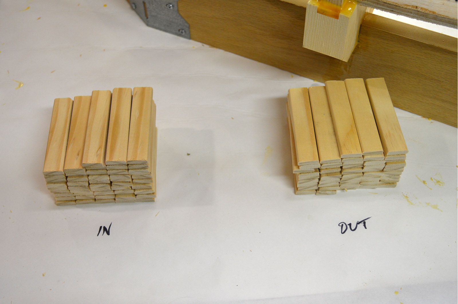
Time to start spacing. The spacers needed to be exactly the same length so the grade is consistent and the track level from side-to-side. Sounds to me like a jig is in order! A temporary zero clearance fence, a 60 tooth blade, and an adjustable stop made cutting spacers a breeze. The spacers were cut to 3.35″ with a 1 degree angle on each end.

Presto, an inventory of inner and outer spacers ready to go. Finally, something moved along quickly in this project.
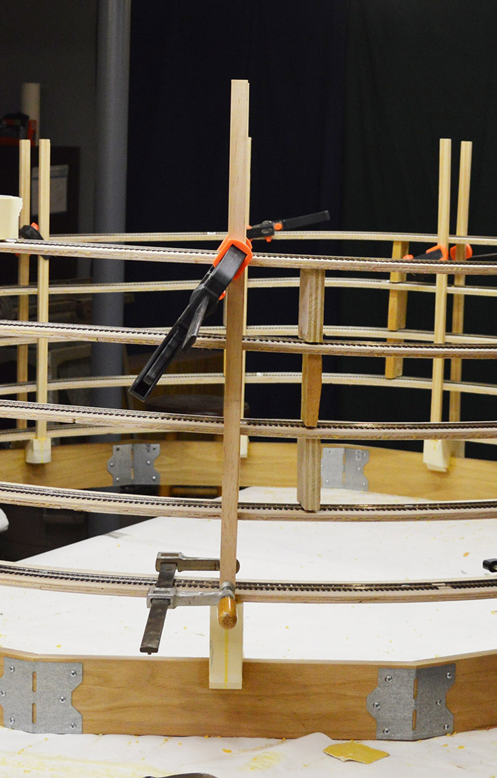
One at a time, starting at the lower exit point and working my way up the helix, I put glue on the backside and both ends of a spacer, positioned it, held it in place with masking tape, and did the same for the other side.
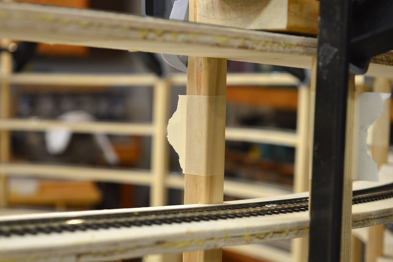
Temporary spacer blocks between the uprights were placed in the the loops above. This allowed me to compress the entire helix on each spacer pair gluing. A wood block protected the track at the top. Clamps were tightened and the setup allowed to dry overnight. I had only enough long reach clamps to do four spacer pairs at a time. Here is a photo of the first spacer pair being installed.
Round and round I went gluing spacers until loops one through four were done.
The helix is a compound grade. Loops one through four are 1.8%. Loop five is 2.0%. That meant the spacers for loop five had to be custom cut to length for each upright. An additional 0.05″ per upright was added resulting in these nine lengths (loop five does not pass over abutments 10 – 12). That’s why the little marks on the fence in the jig picture above. Needless to say, I had to re-cut a few to get them spot on.
| Upright | Spacer (inch) |
|---|---|
| 9 | 3.40 |
| 8 | 3.46 |
| 7 | 3.51 |
| 6 | 3.57 |
| 5 | 3.62 |
| 4 | 3.68 |
| 3 | 3.73 |
| 2 | 3.79 |
| 1 | 3.85 |
The loop five spacers were glued in place.
By this time the helix had become very rigid and felt solid. That’s a good thing. As a final strength adding attempt, I formed large glue fillets from spacer/upright to roadbed at each connection.

There you have it. A boring play-by-play recap of upright installation. I still have to trim the uprights to length but that comes once the helix is in position on the layout. Right now I need to wire this thing with track power. Time to string wire and solder feeders.

Your engineering is always on point, and the execution is whole other level…
Congrats on getting your first helix done, looking forward to seeing the inaugural train run across it… Jason.
Thanks Jas.
hello alan
I am always delighted when I read a new post about your layout. Nice that there is progress.
I approached the construction of the Helix a little differently.
maybe they are interested.
https://flic.kr/s/aHskxfKboS
Martin, your engineering is superb.
Awesome engineering, alan! My question is: How are you going to move the helix into position?
Clark,
Good question. Moving the helix into position will be an engineering challenge in itself! I’ll get it in there somehow.