Remember the post about brake pins I installed to hold trains on the hill at Kitzmiller and at Mittiki mine?
Sooner or later a train was bound to run into a raised pin which could do serious damage to both the train and the pin itself. There are indicators on the respective control panels but they aren’t necessarily in the line of sight when operating a train.
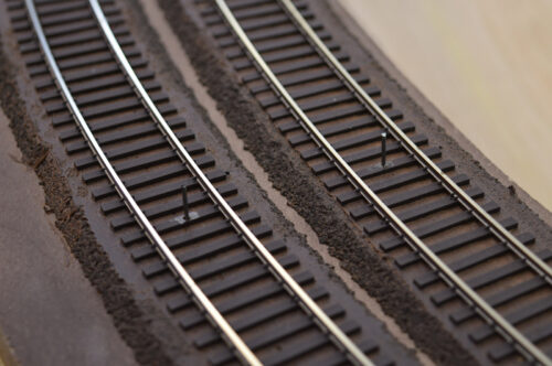
So, I decided to make visual indicators in the form of fusees laying on the track. My first thought was to design a circuit that would randomly flash an LED on the track. Then I remembered the artificial candle my wife has sitting on her desk. Its flickering effect was exactly what I needed. Instead of tearing apart my wife’s candle I chose to source some flickering LEDs from eBay.
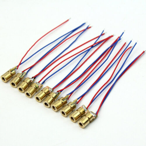
The dome of an LED sticking up in the track would not look good. Additionally, the dispersion angle of the LED light prevents it from being seen well when standing further down the track. My plan was to use fiber optics. Mount the LED below the track and route a thin light fiber up through the track. The fiber optics were a lot of fun to play with but suffered two big problems. First, there was considerable light loss in the coupling of fiber to LED. Second, the end of the fiber had a very narrow viewing angle. It was plenty bright when viewed from directly above but downright horrible from further away (shallow viewing angle). I spent a week trying various coupling methods and modifications to the fiber end. Didn’t make things much better. A significantly brighter light source was needed but that is not an option with off-the-shelf flickering LEDs. Then it dawned on me. If the LED is changing brightness then the current flowing through it must also be changing. A quick measurement confirmed it. Instead of using the flickering LED as the light source, what if I use it to control a bright light source? Lasers are bright and they couple to fiber real well. I purchased some red laser diodes.
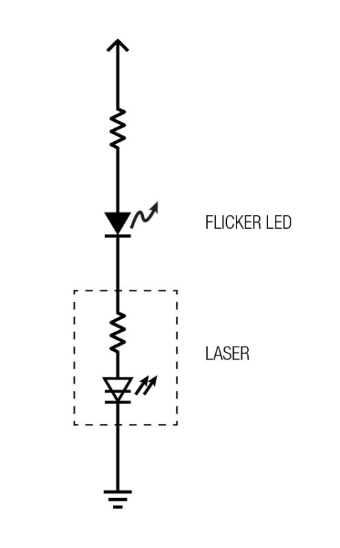
I put the laser diode, the flickering LED, and a current limiting resistor in series so the laser would flicker to the beat of the candle.
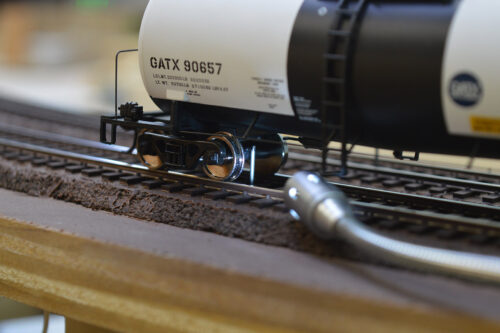
The optical fiber was then coupled to the laser. This combination was much brighter but the poor viewing angle characteristics of the fiber end wasn’t much improved. As I stood there watching the fiber flicker I thought wouldn’t it be cool if I could do away with the fiber altogether and shine the laser directly onto the track. And so my decent into madness began.
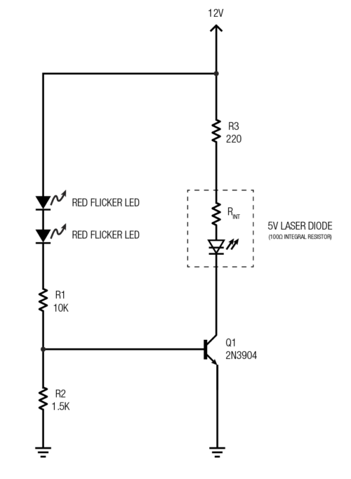
While messing around with the flickering LED I noticed the flickering effect is best when the LED is operated well below its maximum current of 30mA. In fact, when run at full throttle there wasn’t much flickering at all, almost steady light. To get the best flicker effect the current through the flickering LED would have to be much lower which in turn made the laser dimmer. That meant the simple circuit above wasn’t going to get the job done. A transistor circuit was called for. To kick the flicker effect up a notch I added a second flickering LED in series with the first. That really made it flicker!
The new circuit allows independent control of the current through the flickering LED and the laser. R1 + R2 sets the flicker current while R3 sets the laser current. R1 and R2 bias the transistor into its active region (not fully on, not fully off).
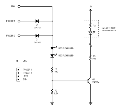
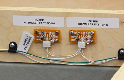
The addition of remote triggering was added to produce the final circuit shown below. The trigger is connected to what would normally be the frog connection on the Tortoise operating the brake pin. A second trigger input was added for future use. The diodes keep the triggers isolated from each other. The link input allows slave fusees to be daisy chained together for simultaneous operation from a single trigger. To make circuit building quick and easy I assembled them on experimenter IC boards cut in half.
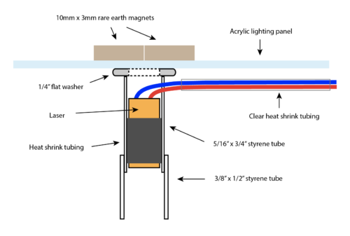
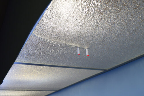
The next task was figure out how to mount lasers above the layout. The acrylic lighting panels are above the layout and I was none too keen on drilling holes in them. Some form of adjustability is needed so holes weren’t going to work anyway. Here is what I came up with:
No holes in the acrylic and easily positioned. Just what the doctor ordered.
With temporary fusees and their ash piles in place this is the final effect:
The video doesn’t do the fusees justice. They are insanely bright and best of all they catch your eye even from clear across the room. I’m happy with the results. When it comes time to ballast the track I’ll make more accurate fusees and ash piles.
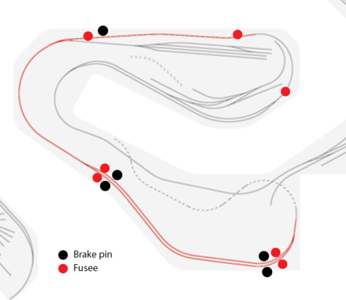
The LK&O now has seven fusees – 4 at Kitzmiller, 2 at Mittiki mine, and 1 in Lapeer. The fusee in Lapeer is to warn of a pin up at the mine since the mine cannot be seen from Lapeer. Raising a pin on either end of the Kitzmiller main or siding will light the fusee on both ends of the main or siding.
So there you have it, my fun adventure down a rabbit hole. See ya next time.

Alan – your layout has reached another dimension what with the operating fusees! Clever solution, also! Very entertaining layout you have evolving here…
Clark, I’m glad you said entertaining. That is the primary reason for having a train layout is in not. Thanks for following along.
RIGHT ON!
Hi Alan,
I have enjoyed all the webpages you have sent me.
Please, keep the LK&O RR webpages coming!
Roland
Wow – Really neat idea to add in the fusee for warning the brake pin is up! Great idea – ingenious design!