It has been a while since the last post but that doesn’t mean I haven’t been working on the railroad. Just happen to be doing slow progress tedious work at the moment specifically wiring control panels.
The first wiring task was to determine the desired brightness of the panel LEDs. They need to be bright enough so they can be easily seen at full room lighting but not so bright they look like beacons when the room lights are down. Add to this, different color LEDs have different brightness at the same current. Another factor to consider is the human eye’s sensitivity to different colors. Our eyes are especially sensitive to green. Sure enough, when I laid the different color LEDs side-by-side each driven at a uniform 10mA they did not appear the same brightness to my eyes. The green was insanely bright, the purple was very attractive but also very bright. The red and yellow were the closest to each other in brightness and were not as bright as green or purple.
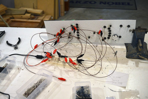
Through trial and err I changed out LED resistor values on this test subject panel until I arrived at an acceptable brightness and evenness across colors.
The resulting values are:
| Green | 22K Ω | 0.4mA |
| Red | 5.6K Ω | 1.5mA |
| Yellow | 3.3K Ω | 2.6mA |
| Purple | 8.2K Ω | 1.0mA |
| Blue/Red Flash | 5.6K Ω | 1.5mA |
| Red Flash | 5.6K Ω | 1.5mA |
[EDIT 15 Apr 2017] Current values in above table corrected to include voltage drop of series diode.
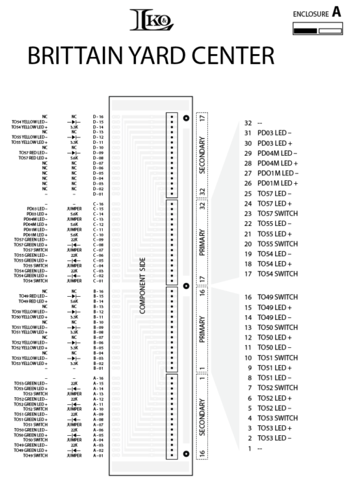
I made a hook-up diagram for each panel/connector board to guide me as I place components and attach wires. These same hook-up diagrams will be used when it comes time to install the panels on the layout and attach the module wiring.
Here is a PDF of the connector hook-up file.
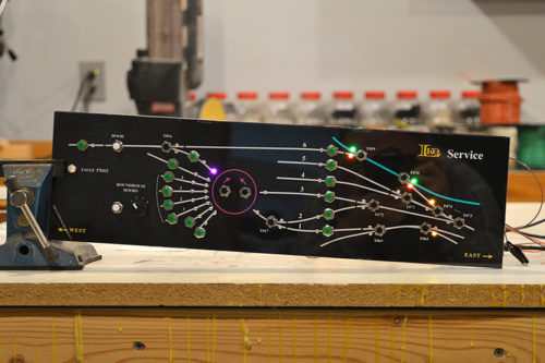
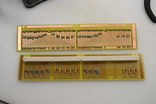
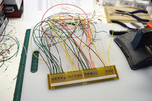
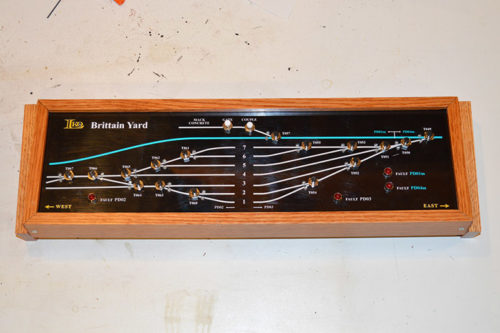
With resistor values known it was time to assemble the first connector board. I started with the Brittain Yard Center panel. It has a lot going on so two connector boards are needed. The components fit a lot better than I imagined they would. Plenty of space. Resistors are for LED current limiting while the diodes prevent reverse bias of the LEDs.
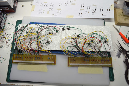
Next, I added the 24 gauge wires that will connect to the switches and LEDs. Color coding the wires helps eliminate errors.
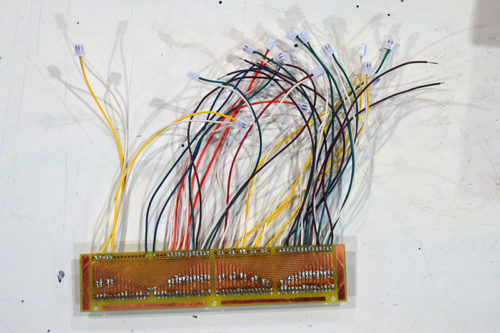
As a side note, I first tried using JST style PH connectors (sometimes called Dupont connectors) to connect to the LEDs as shown below. That was an abysmal failure. The pin spacing is right but the LED lead is just too light gauge for the connectors to get a good grip. It was like playing Whack-a-Mole trying to get all of them attached. Bump a wire and the connector popped off. I ditched the connectors and instead used trusty ole soldered point-to-point wiring. It’s slow but it works.
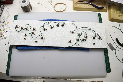
Before attaching the connector boards I first ran V+ to each switch on the panel.
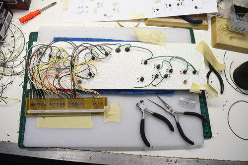
Then came installation of the left side connector board.
The process goes like this:
- Cut wire to length
- Strip insulation from the end
- Tin the wire
- Fold into a small hook
- Fit over the LED lead
- Tighten with needle nose pliers
- Solder
- Trim LED lead to length
- Bend lead away from other leads
Repeat, repeat, repeat.
Then the right hand connector board. If you recall my original idea was to use printed circuit board for the back of the panel. That would have eliminated all this wiring. But alas, it was not meant to be. Wires, hundreds of wires, it is.
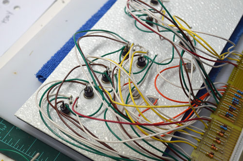
A close-up shot of the wiring. Easy access at the beginning, crowded near the end. Sometimes it is quite challenging to get the soldering iron in there without touching another wire.
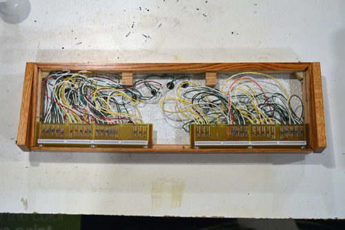
Once everything is soldered it is time to place the assembly in an enclosure. #4 x 3/8″ sheet metal screws attach the connector boards.
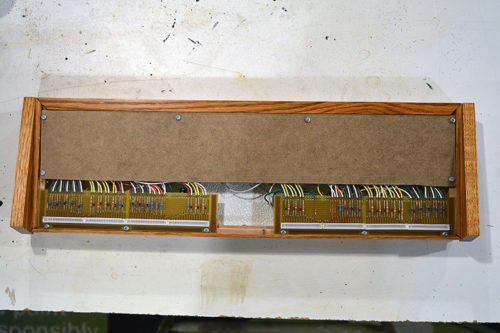
A close inspection is made to make sure no LED lead has moved and is touching any other. Then one at a time I test each connector pin pair to make sure the corresponding LED lights or switch works. When satisfied all is right the rear cover is put into place.
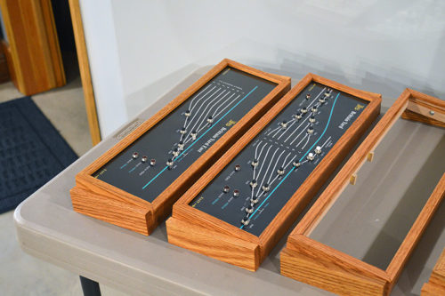
And there you have it. A completed, ready to install control panel.
2 done, 14 to go!

What, no conformal coating??? Seriously Alan, job well engineered. Hard to believe you are able to get all that wiring and components in such a compact space. Looks great!
Ha! Nope, no coating. Not that hi-tech around here. 🙂
Hi Alan
Great job!!
About leds and Dupont connectors
Try to solder or crimp Male Pins to leds leads, one led insulate with thermo and the connectors work fine
(http://hobbycomponents.com/cables/562-male-pin-connector-for-dupont-jumper-wire)
Claudio,
Great minds think alike! I actually tried the male pin idea. The only advantage to the connector is they can be disconnected and the LEDs easily removed from the panel. With male pins at the base of the LED leads they no longer fit through the back panel hole nullifying the advantage. The LED leads fit tight against the sides of the hole. If I place the male pins sufficiently high on the LED leads to allow squeezing together to fit through the hole then the LED leads deform when fitting the female connector. My eBay Made-In-China LEDs have very small gauge wire leads. The insertion force is greater than the LED lead strength if you are not pushing exactly straight down which is more difficult than it sounds to do repeatedly.
Thoughts?