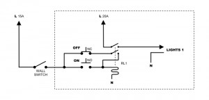
Remember this schematic from a few posts ago?
Since then I have made great strides in the lighting control implementation. There will be a full post following shortly that will cover the complete installation. I want the installation finished before I post an entry so I can have pictures of it all. For now, this post is about the wiring of the relay panel only.
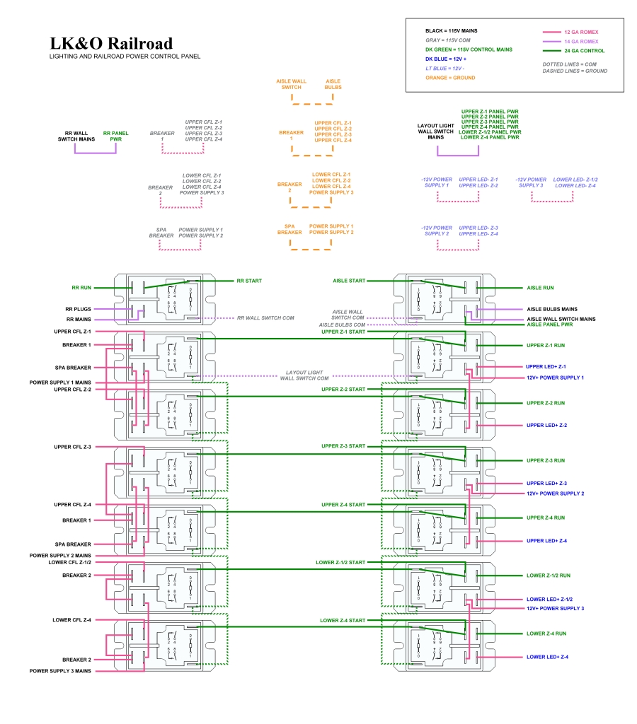
Using the wiring idea from the picture above, I created a schematic for the relay panel. It looks more complicated than it really is. This arrangement gives me independent control over:
- Upper deck CFL & LED lighting in 4 different zones
- Lower deck CFL & LED lighting in 3 different zones
- Aisle lighting
- Railroad power
As designed, the wall switches next to the door arm the lighting control system but don’t actually turn on lights. The control panel switches turn on the lights. The wall switches do however allow me to turn off everything with the flip of a switch. Cool! OK, so railroad power is not lighting but it just seemed logical to include it in the arrangement.
The panel is fitted with relays and mounted in place. Wiring has been run. Tonight I begin wiring the relay panel. Don’t miss the next post. It will be a biggie with all kinds of lights, switches, relays, and wiring goodness!


Leave a Reply