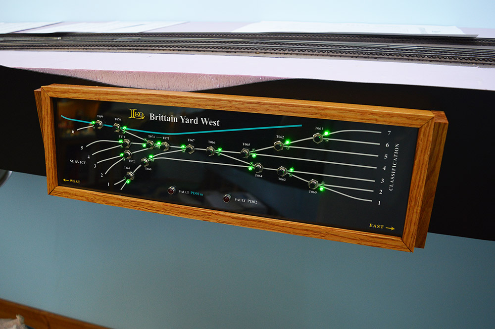
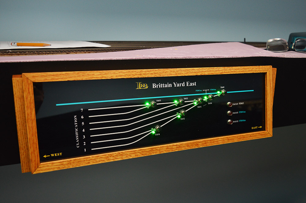
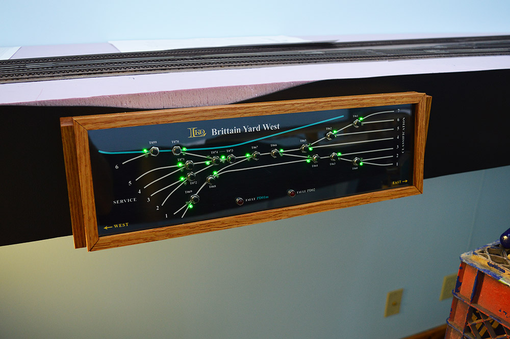
Three months into my retirement and I have finally made it into the train room to get some work done on the layout. I have the first two control panels working – Brittain Yard West and Brittain Yard East. Woohoo!
It is satisfying to see everything starting to come together. Work on the control panels started almost four years ago. My, how time flies. I am now one step closer to a proper operating train layout. No more touching bare wires together to make turnouts move. So nice.
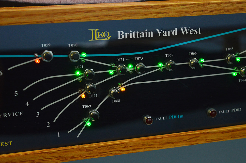
BTW… on the LK&O a green indication means the turnout is set to normal or through route. Red and yellow indications mean turnout is set to reverse or diverging route. Yellow means the turnout can be left in the reverse position when your train leaves. Red means the turnout must be returned to the normal position when your train leaves.
Installing connector contacts
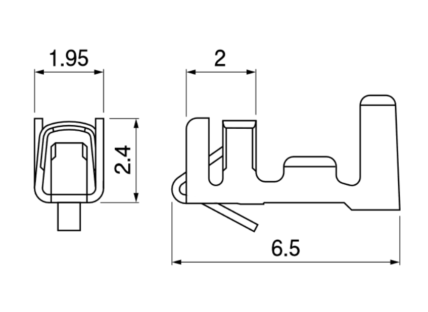
If you followed the control panel build you know I am using JST series XH connectors to connect the panel to its respective track module. XH are crimp style connectors. Very small crimp connectors. The illustration below shows just how small. The dimensions are millimeter. The total wire crimp length is only 2mm. 1mm for the insulation and 1mm for the bare wire. Not much room for error during assembly.
I have never been a fan of crimp connectors. Rarely do I use them and when I do it is usually in a noncritical application. But since I have over a thousand connections awaiting me and the terminals are crimp by design, I decided to give crimp a try. I bought a ratcheting crimp tool that is advertised as suitable for XH and a few other size JST connectors.
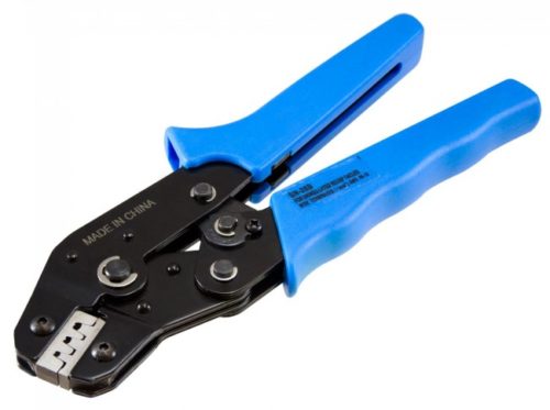
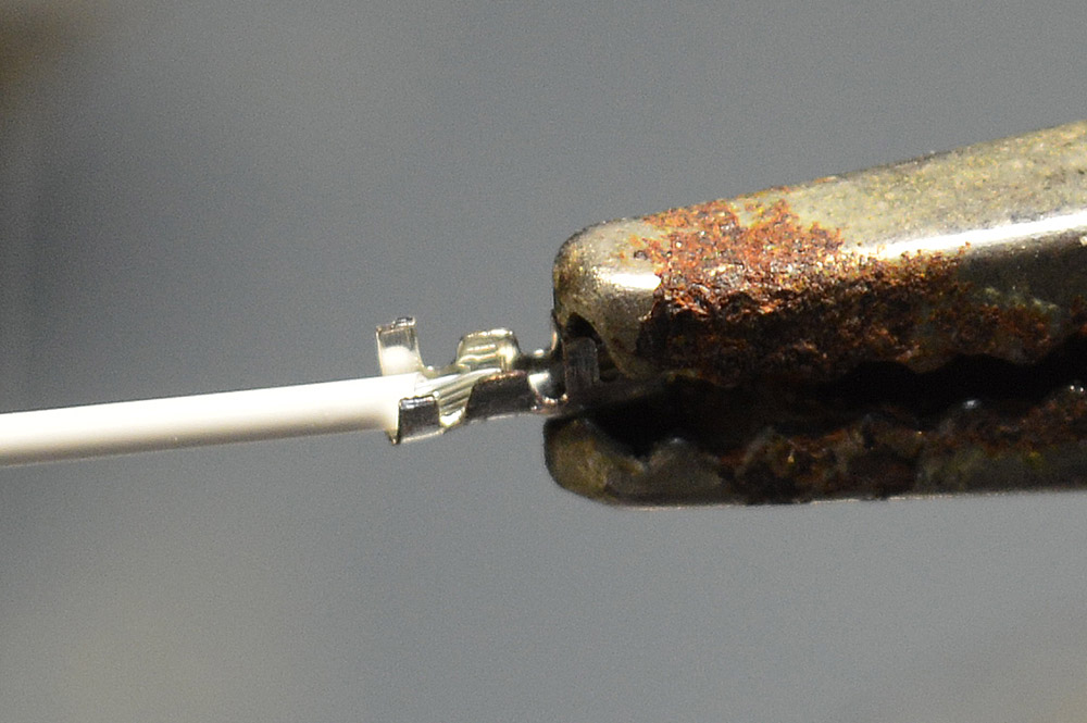
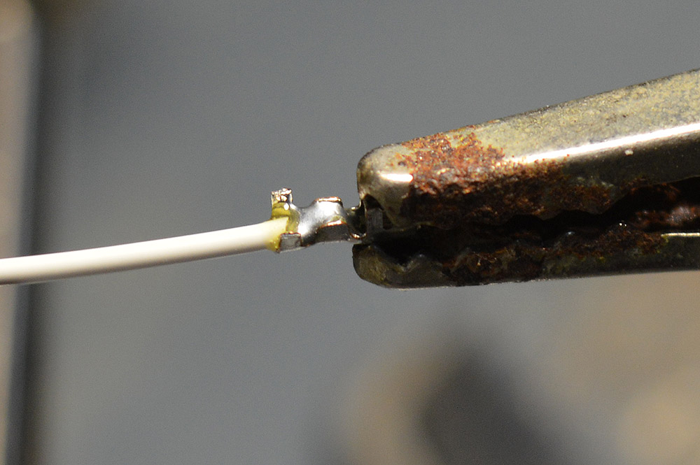
I have to say, I don’t care for these pliers. While they do work, I found it challenging to get consistent results. Specifically, getting the wire depth correct. The 1mm stripped wire must be exactly in the right place otherwise if too deep the header pin bottoms out on the wire, if too shallow the crimp doesn’t catch the insulation well. The jaws block sight of the wire positioning. It is a judgement game of how deep to insert the wire. That and the fact the pliers are big and bulky for working with such tiny contacts makes them that much less fun to use. After messing around for a while making test crimps, many of which failed, I finally said screw this. I’m resorting to my old ways. Something I know well – soldering.
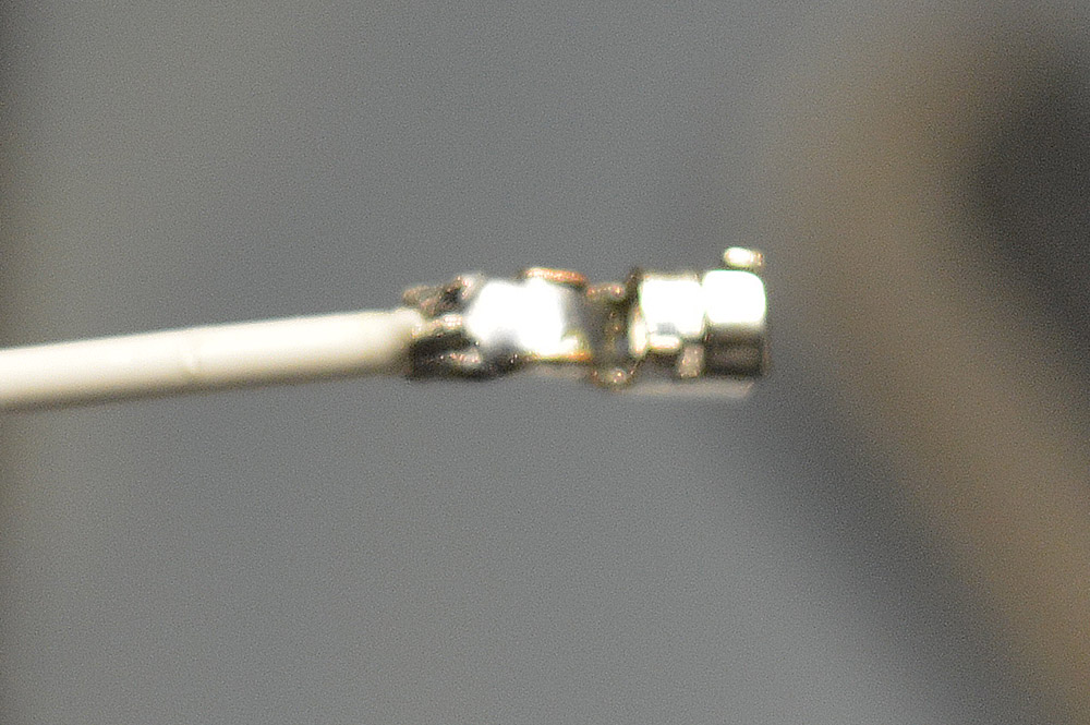
Soldering crimp connectors is generally not a good idea. Electrically it is fine, mechanically it is not. Over time the conductor can have a tendency to break at the end of the contact if the wires are subject to vibration or frequent handling. Fortunately, my panel wires will not be subjected to either so soldering crimp contacts works fine in my application. Plus, I think I can retain the insulation crimp feature even though the contacts will be soldered. This work calls for the OptiVISOR!
With full view of the contact it is no sweat to get the wire in the proper place and the solder in just the right spot. The one modification made to the contact is cutting the insulation crimp wings to one half length. A proper crimp of a XH contact rolls the wings twice over themselves. I’ll be manually crimping the wings in a typical fold over so shorter wings are needed.
Mobile workstation

With a repeatable process proven to work it was time to go all out production. My process calls for a lot more tools than simply a pair of crimping pliers. I dislike placing tools on the layout itself so a mobile workstation was in order. I have no such mobile workstation. Hmm…

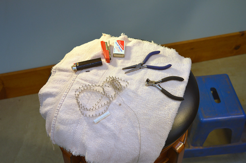
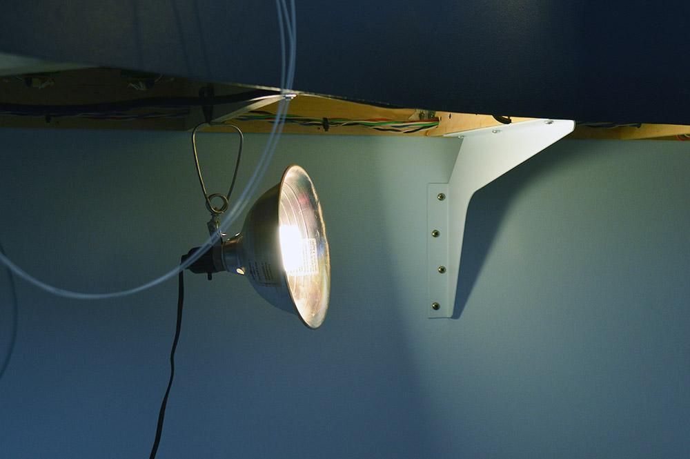
Yep, four milk crates and a pole held together with a whole bunch of wire ties makes for a fine workstation. Add a stool for hand tools, with a towel to keep tools from sliding, and a couple 100w lights and you’ve got yourself a genuine Red Green traveling workstation! Complete with professional soldering iron holder. 😛

Wire labeling
When the track modules were originally constructed and installed I left an appropriate length of wire with which to hook to the control panel. The wires were temporarily identified with Avery #8167 labels on masking tape.
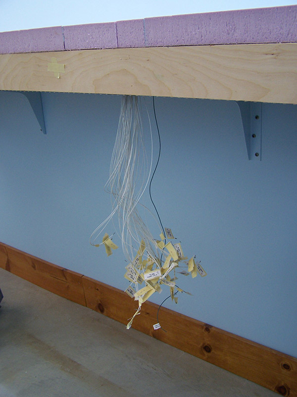
Early on I learned the adhesive on Avery inkjet labels is temporary at best. Hence the masking tape. An Avery label wrapped around a small gauge wire falls off within a month. Now that it is time for permanent labeling I want to make sure they don’t fall off and I certainly don’t want masking tape. I still have to use Avery labels simply because I have no other practical choice. Positioning masking tape or a label so that it aligns when folded over a wire is no trivial adventure either I also learned.
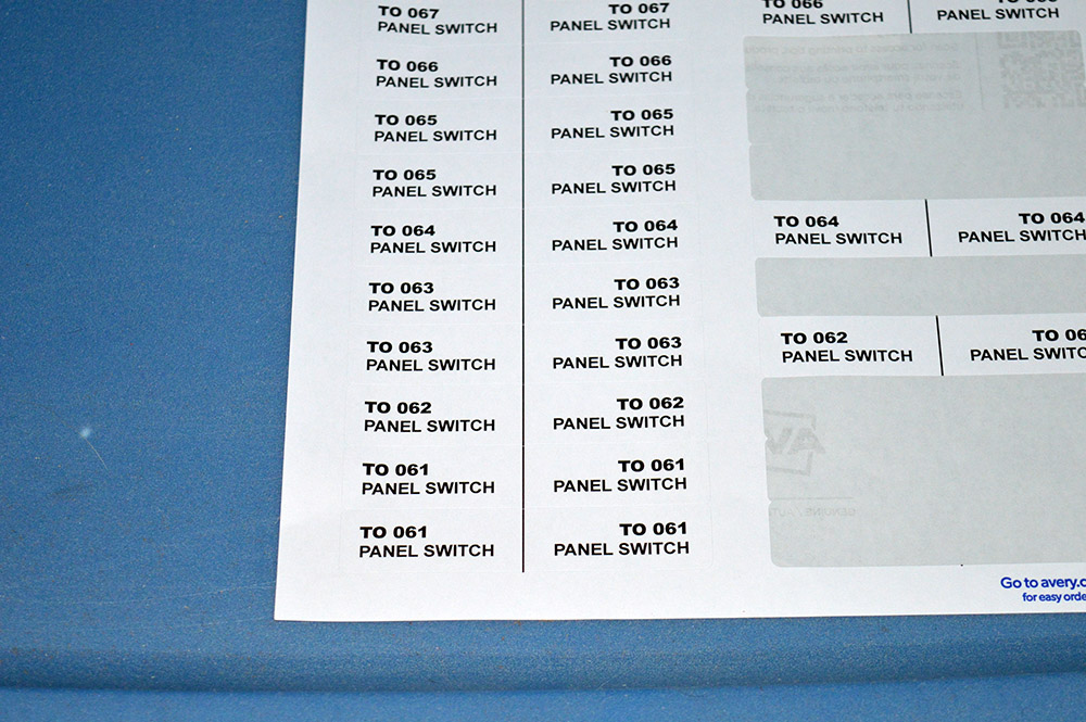
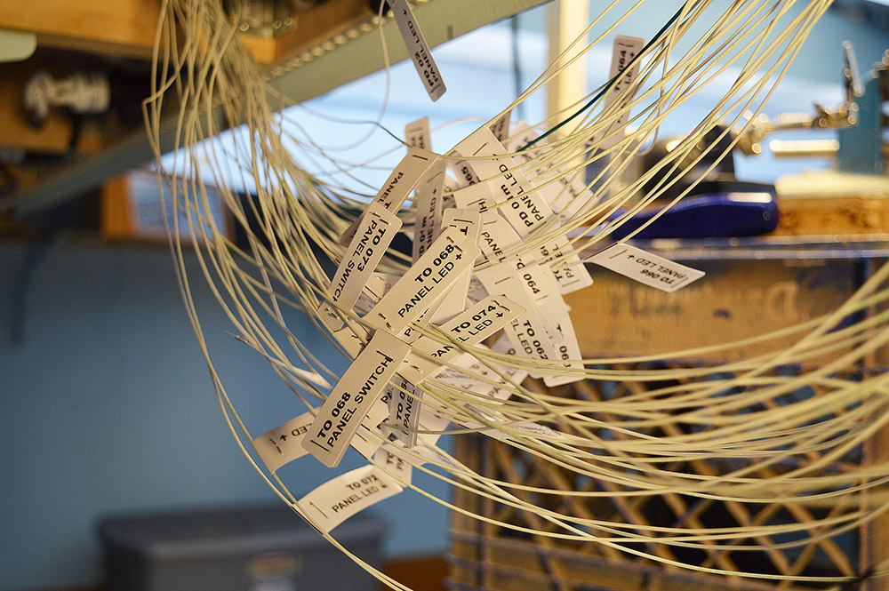
Here are my solutions. This time around I used Avery #94210 labels because they are wide enough to wrap and to print the info twice i.e. double-sided wire label. The wrap alignment was aided with a printed line down the center of the label. Align the black line with the wire, wrap, squeeze, and presto a nice evenly wrapped label. To keep the labels from falling off I stapled at each end.
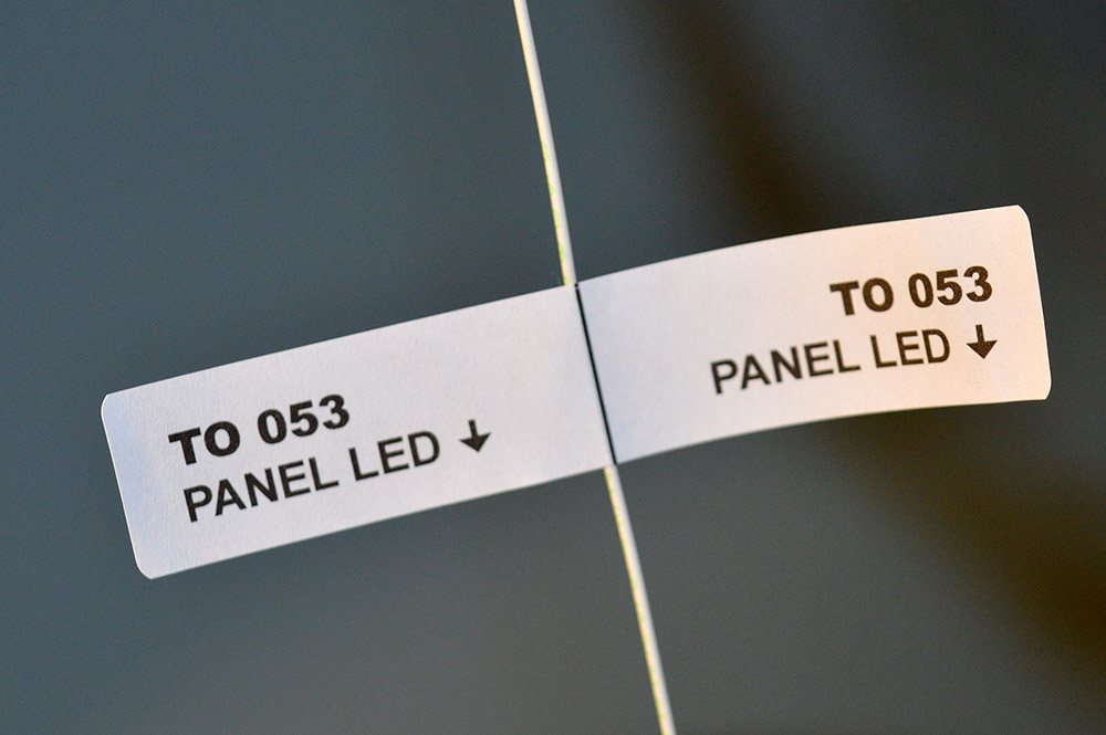
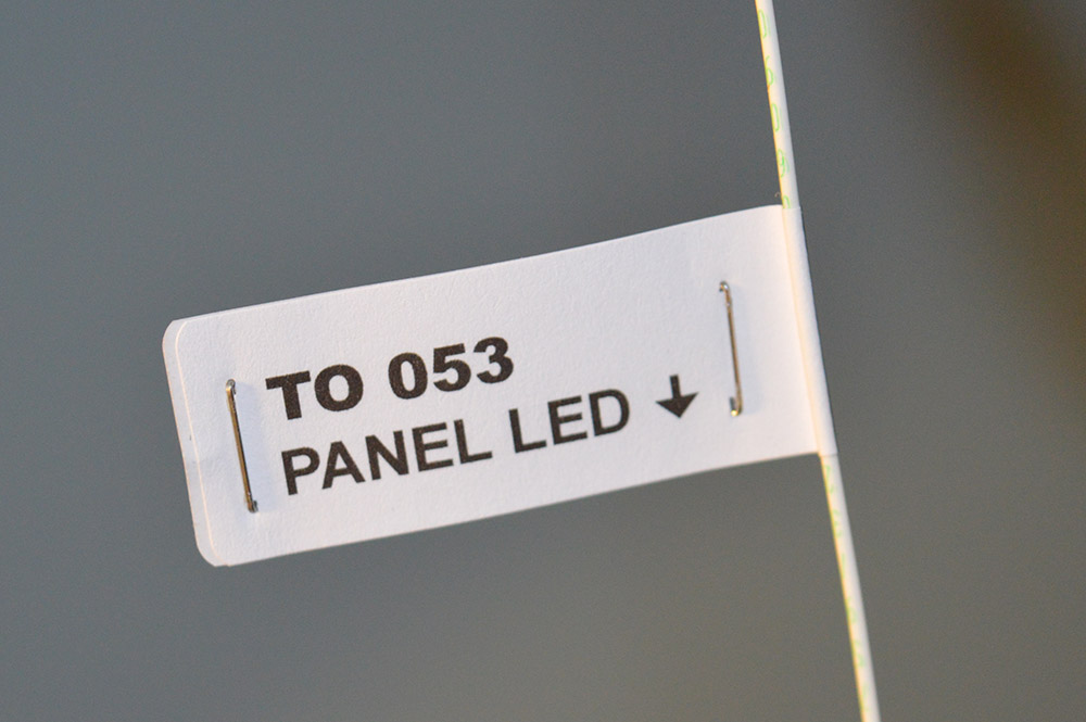
Now, even if the adhesive totally fails, the label won’t come off the wire. At worst, it may slide down the wire but as you will see next this is a non-issue.
Wire routing and assembly
I wanted to start with the most complicated panel because it would have the greatest number of wires to deal with. If it is practical to wire the most complicated panel then the other 15 panels should work as well. If there are a lot of wires then there is also a lot of labels. Will the finished harness fit and tuck away sight unseen, not block the lower deck lighting, and still be removable with its track module? The Yard Service panel is by far the most complicated but since I have yet to build the Yard Service track module that wasn’t an option. So, I choose the 2nd most complicated panel – Brittain Yard West.
Once a harness path was identified I then located a spot where the labels would reside i.e. keep all the labels in the same area, away from lights, away from Tortoise movements, etc. With path and label position decided, I repeated the following process for every live primary pin on the panel. The secondary pins will come later.
- Untangle wire from original bundle
- Cut off temporary label
- Route wire
- Mark label position
- Cut wire to length at panel
- Remove wire from harness route
- Apply label
- Strip 1mm of wire end, clamp in alligator clip
- Cut off 1/2 length of insulation wings on contact, clamp in alligator clip
- Align wire to contact (move the 3rd hand and vise into position)
- Solder contact
- Crimp insulation wings
- Insert into plug
- Test insertion into loose pin header
- Repeat, repeat, repeat…

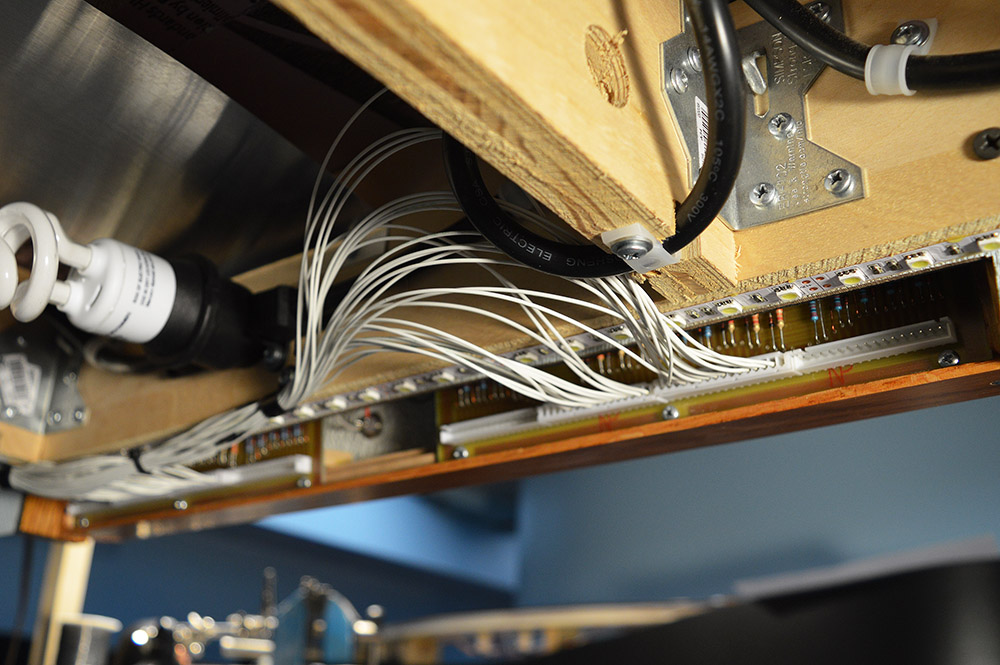
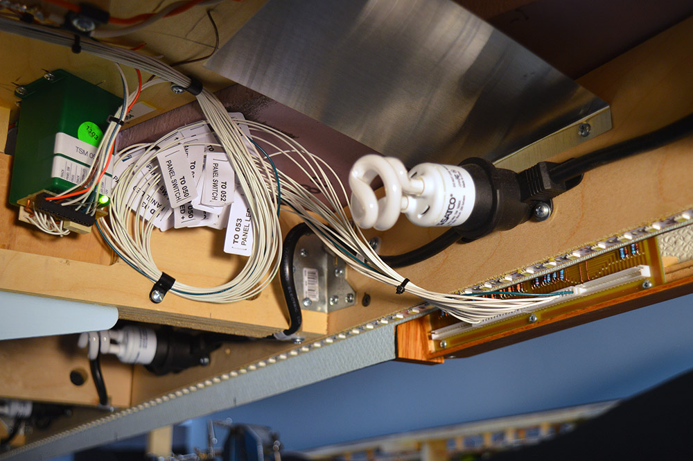
Here is what it looks like after connecting all the contacts but before placing the harness into final position. Bit of a mess, eh? You can see the nylon clamps installed along the benchwork as a result of determining the wire route.
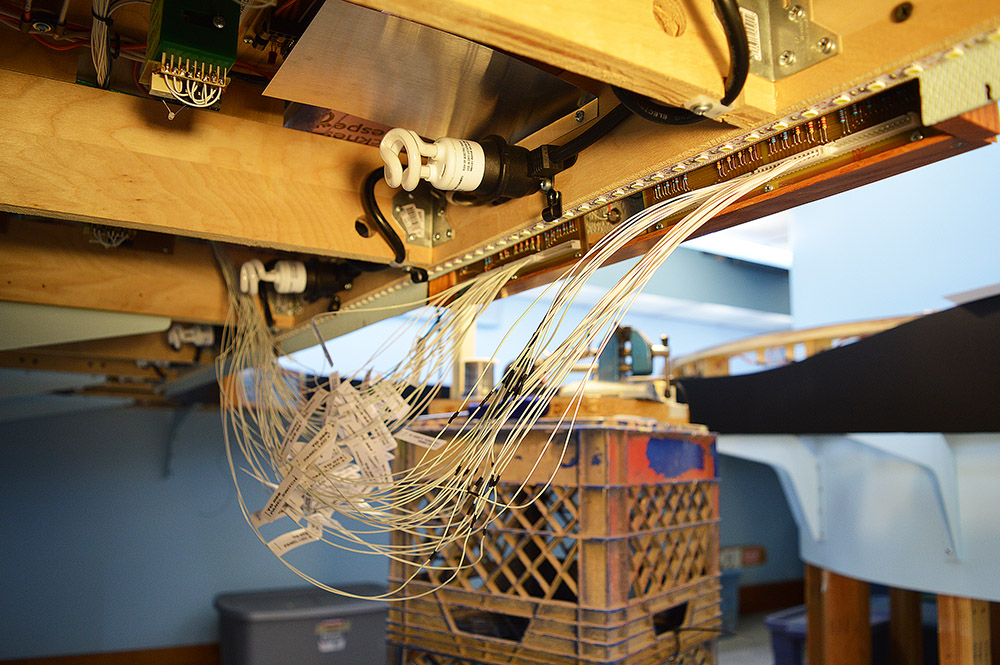
Interesting note. Late in the game I shifted the Brittain Yard West panel left about 12″ on the fascia from where the plans called for. This caused some of my track module wires to be too short. That explains the little black heat shrink covered connections you see in some of the wires. Had to add the missing foot of wire.
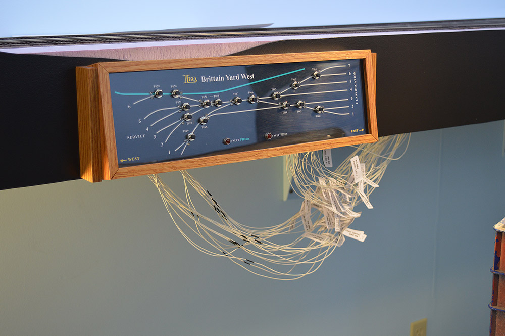
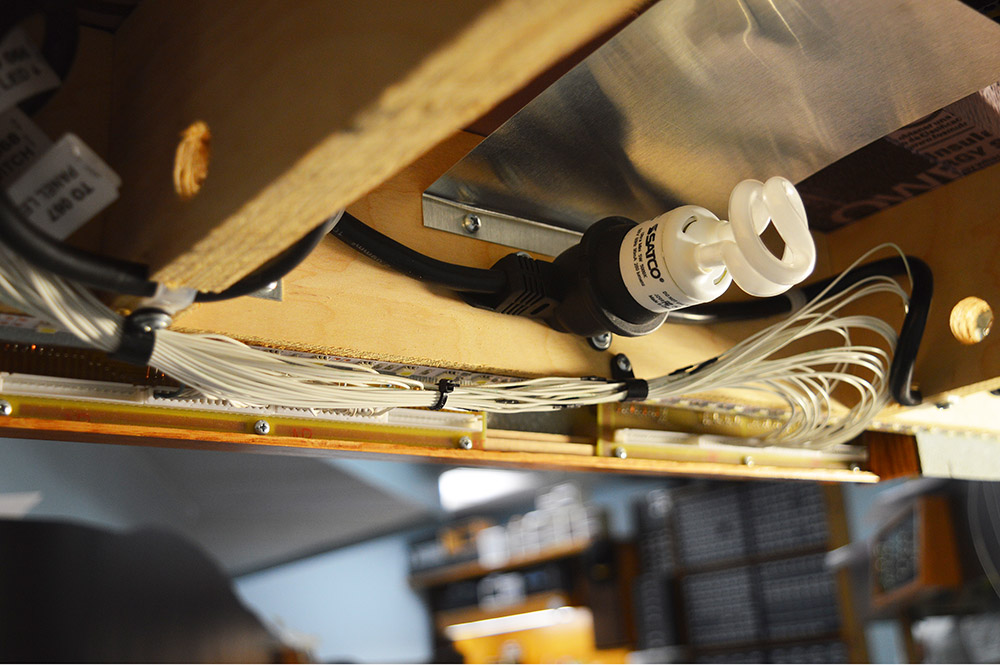
Here is the wiring harness in final position:
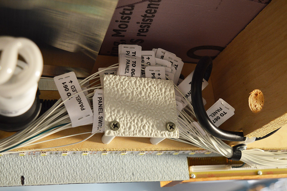
Sure enough, there were so many labels that they were unruly while positioning against the benchwork up out of sight. Fixed that with a quickie-made label holder! Slide in, slide out like a napkin holder.
Hit the power button and viola! I have my first working control panel. Have to admit I played around pushing buttons watching turnouts move and LEDs light up for quite a while.
Next panel
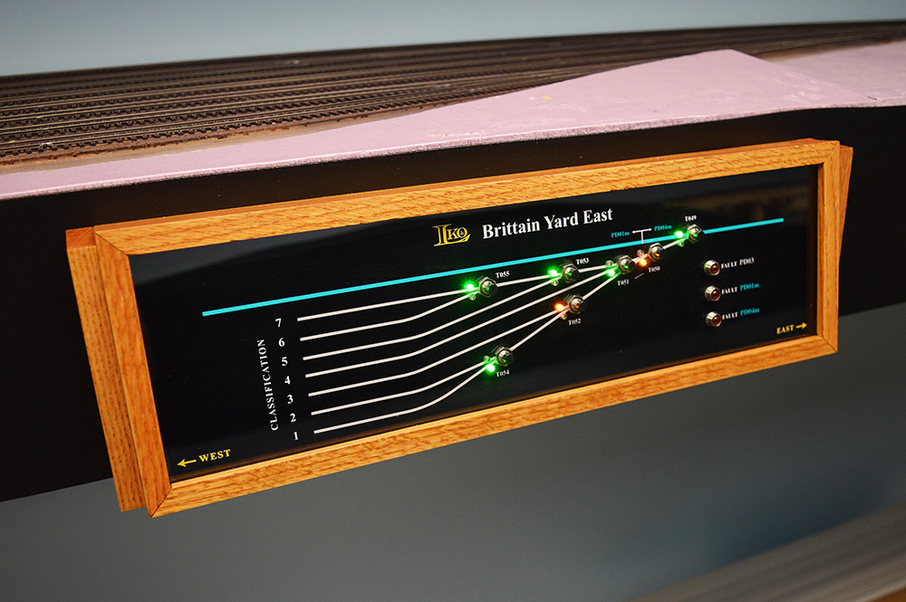
Beginning the lather, rinse, repeat process around the layout I moved on to the Brittain Yard East panel. It is much simpler and took much less time to wire.


Time to play
With both ends of Brittain Yard operable from control panels I can now work the yard if I wish. May have to sort and block some cars before I move on to the next panel. 😉
Only 976 contacts yet to go! See you next time.

Retirement is great, just remember keep some time for yourself. 3 months in and you finally post but hey you are retired, no rush. Suggestion for your tools and to be mobile, go to Michael’s and look at the rolling storage units. I can’t post pictures here but I have a nice compact 3 shelf metal unit from them.
Have fun, stay safe
Tom, I could have bought something but chose not to. It would just be one more thing to store in the basement and space is running low. The crates will go back on the crate pile and the stool will return to its spot at my workbench.
Hey Tom, great to see you back on those panels. I envy those panels and I’m still in the thinking process. The fun part of retirement is being able to enjoy every moment without rushing. Keep us posted on more of those panels. Thanks.
Sorry Tom, meant Allen