It’s all in the presentation they say. I agree. What more is a model railroad than a presentation of an animated miniature world?
I like the shadowbox effect when used on a model railroad. It really draws your eye to the scene. The shadowbox idea makes hiding the layout lighting much easier too. In my case it will also support the drop ceiling. Early on I decided my railroad would be a shadowbox style presentation.
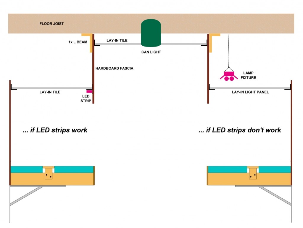
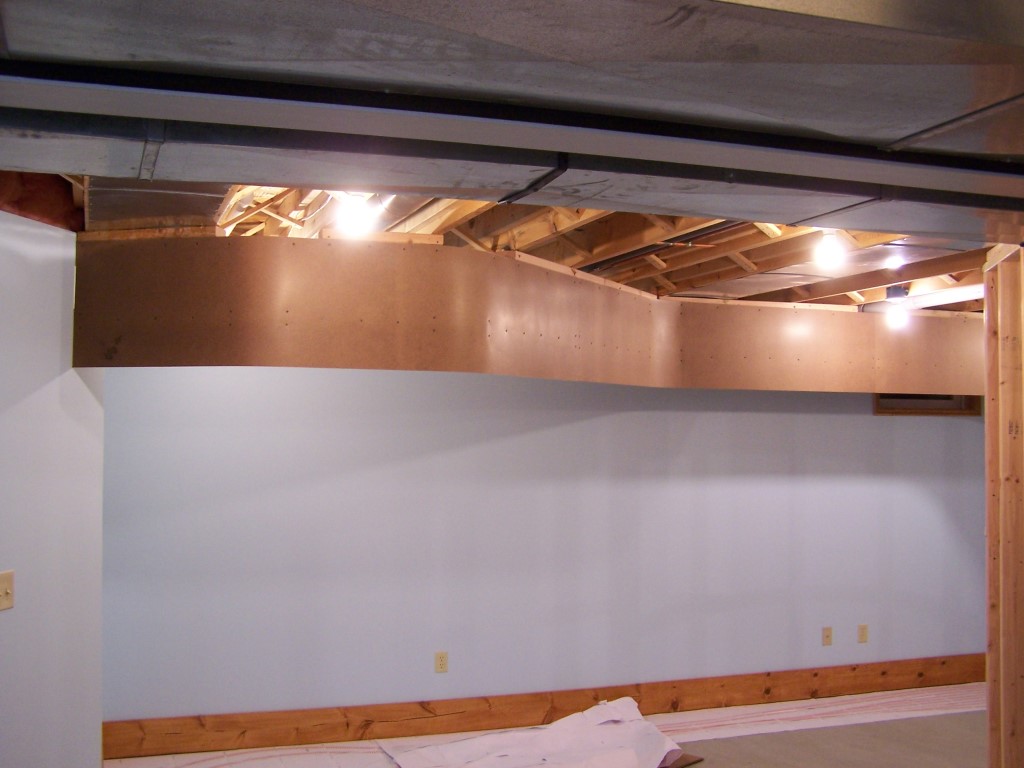
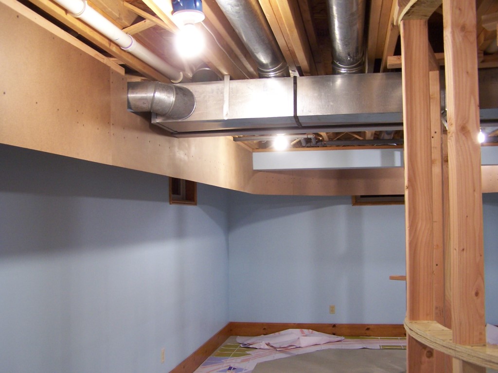
Originally, my thought was to build a 12″ stud wall complete with plywood curved corners the same as the peninsula wall is built except this one would hang from the ceiling joists. To this would be attached 1/8″ hardboard (Masonite). No doubt that would have worked and been very sturdy but it would also have been quite time consuming and material intensive for such a light duty task. Hardboard becomes amazingly rigid if bent into a tight radius. I am using this fact to my advantage and to eliminate the need for a proper wall for the upper valance.
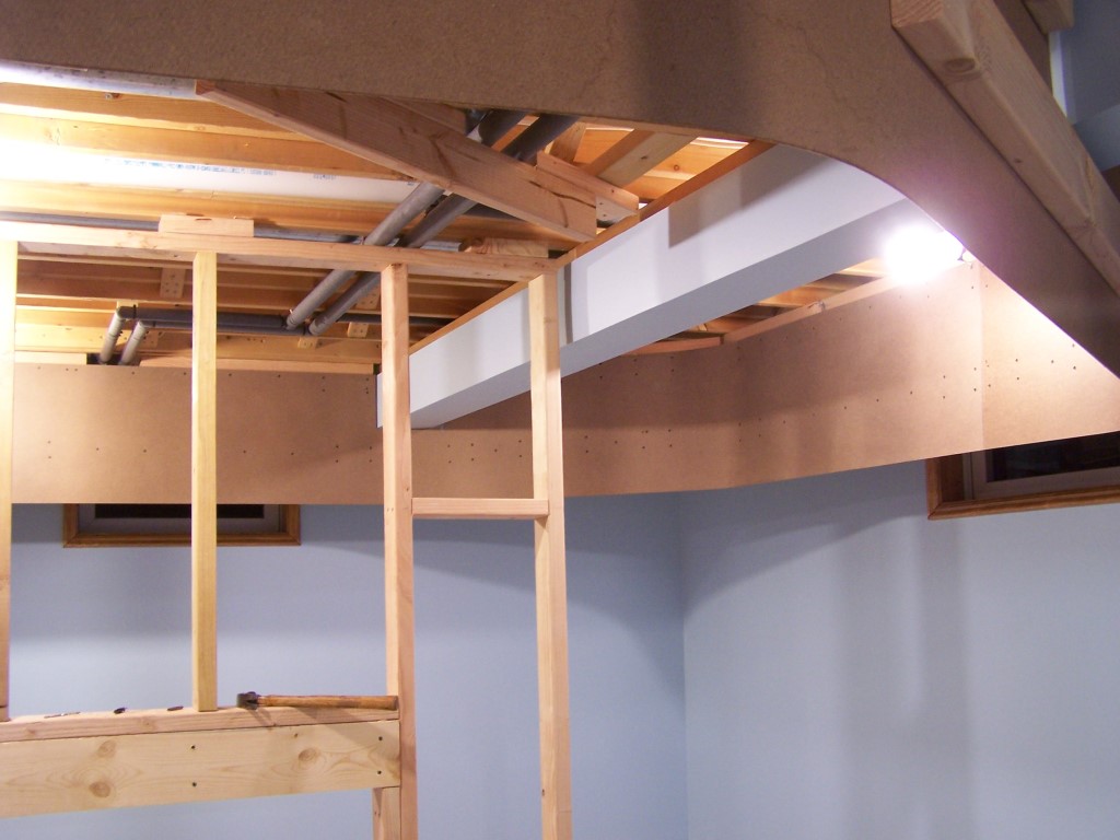
To the ceiling are secured 2″x4″ L beams. The end of any given L beam vertical section is positioned according to the layout marks on the floor. I am using a plumb bob to make the alignments. Measuring the length of the L beam verticals is easy. I simply use the pencil mark outline of the bench work plan on the floor. The L beam horizontals are sized to span at least two floor joists albeit at odd angles in some places. 2×4 blocking is used where the L beam ends mid span between joists. The horizontal and vertical components are assembled and then screwed to the floor joists once again using the plumb bob to get the alignment spot on.
Another 2″x4″ is screwed on the backside 5″ up from the bottom of the valance to force the hardboard to lay straight on long sections and also to force the hardboard to make evenly proportioned curves (from top to bottom). Both the L beams and the straightening boards span the hardboard joints. The ends of the straightening board are vertically aligned with the ends of the respective L beam vertical. Countersunk drywall screws hold the hardboard to the 2×4’s, 3″ deck screws hold the L beams to the floor joists. Assembly is relatively easy and moving along quickly.
You can’t believe how rigid the valance is already. Sure am glad I didn’t spend the time and effort to build a 12″ stud wall all the way around. Once the drop ceiling grid is in place this assembly will be like a rock. This is working out sweet.
It doesn’t look real sexy at the moment. Use your imagination… drywall mud on the screws and joints, couple coats of Horizon Haze blue paint, drop ceiling track and panels in place, can lights down the aisle. Ah, much better, huh? Stay tuned!


What is the distance from the bottom of the valance to the top of the layout? I.e. the “window” into the layout
The distance from the bottom of the lighting valance to the layout upper deck zero elevation is 22″. The bottom of the valance is 75″ above the floor, the layout zero elevation point is 53″ above the floor.