Not all ideas can be gems, right? Such is the case with my idea to consolidate 20 sensors to one board using shielded cable for the connections.
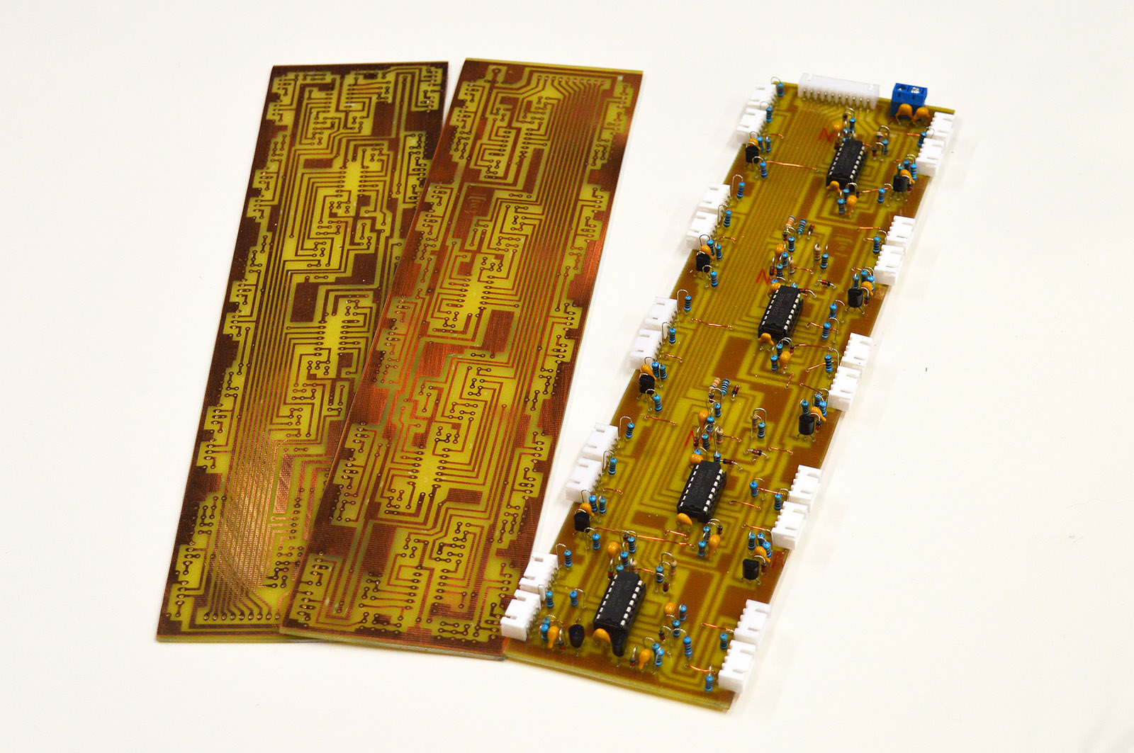
I etched three boards and assembled one. Everything went smoothly during the assembly.
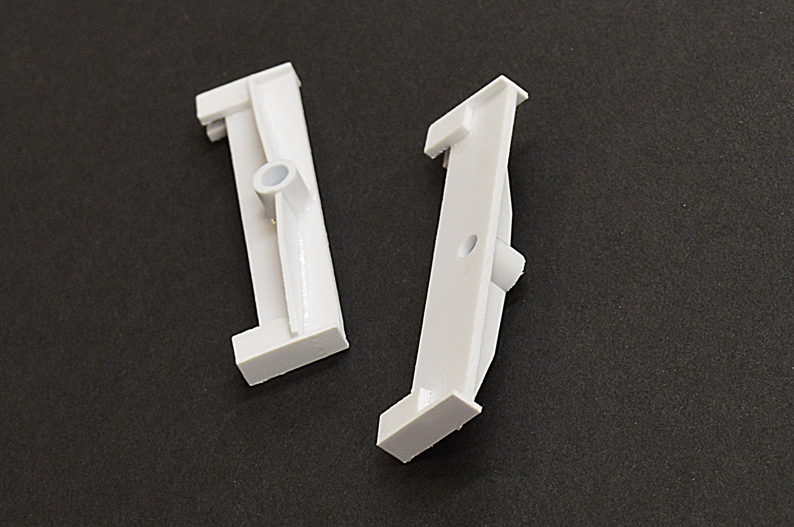
I fabricated some mounting brackets from 0.080″ and 0.040″ styrene. Hit them with a shot of black paint to give them a finished look.
Mounted the board onto a helix upright.
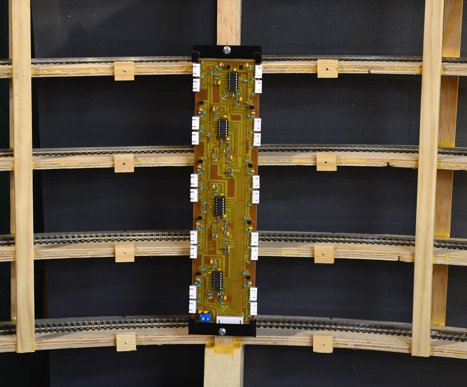
I then began soldering cable onto the sensors and mounting them. This is where my engineering oversight came to the forefront. I failed to take into account the locking strength, or lack there of, of the JST connectors at the board. I wasn’t keen on the idea of shielded cable from the get-go but remote sensors would not work reliably without it. I imagined with enough wire ties and cable clamps I could route it neatly in a way that didn’t restrict access to the track. Wrong! The connectors would not tolerate the least bit of sideways pressure from the cable.
You can see in the picture below what was happening at the connectors. Even though the locking tabs are still engaged, the connector screams future failure point. The slightest bump of the wire is all it took to disengage one or both locks.

I tried various lengths and routes to no avail. This was going to be a spider web of wire if I continued. Even though the wire arrangement and central circuit board works electrically, it doesn’t work physically. Time to cut bait on this idea.

The effort won’t go to waste however. The central board and shielded cable will work fine on the north helix since it is only a turn and a half in length and the board and cable can be mounted differently thus eliminating the wire tug on the connectors.
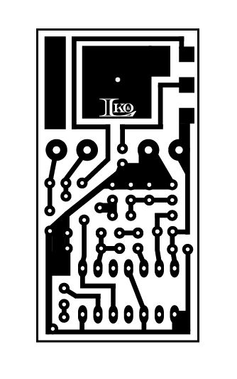
So, I went back to the original idea of a complete, independent circuit at each sensor. Means a lot more circuits, 120 to be exact, but totally eliminates the shielded wire and long interconnect runs. For this I needed a new circuit board. One as compact as I could make. This is the result. It measures 1″ x 1-7/8″.
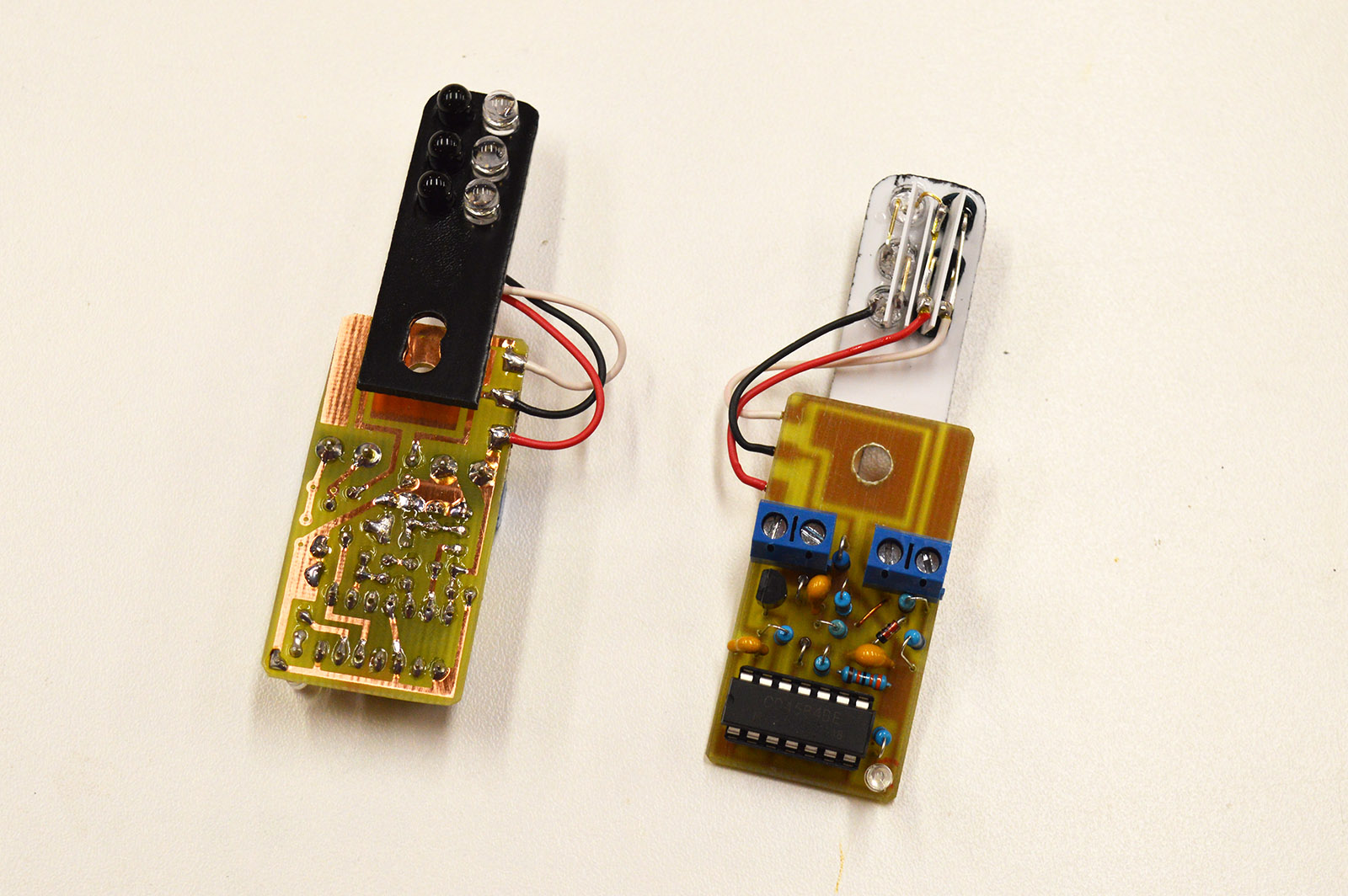
For testing purposes I mounted two completed sensor circuit boards hooking them up with some temporary wiring. Because two individual sensors act as one there had to be a way to daisy chain them together. That is the green wire you see running between the “master” on the left and the “slave” on the right (brown wire in 2nd picture below).
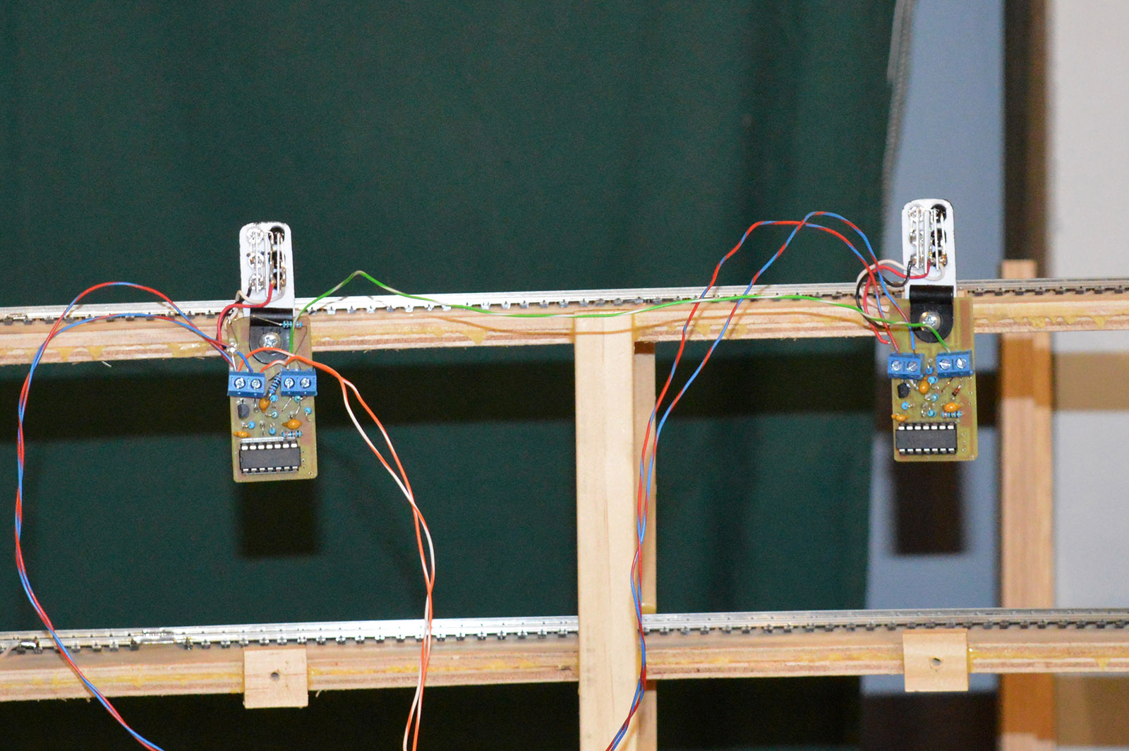
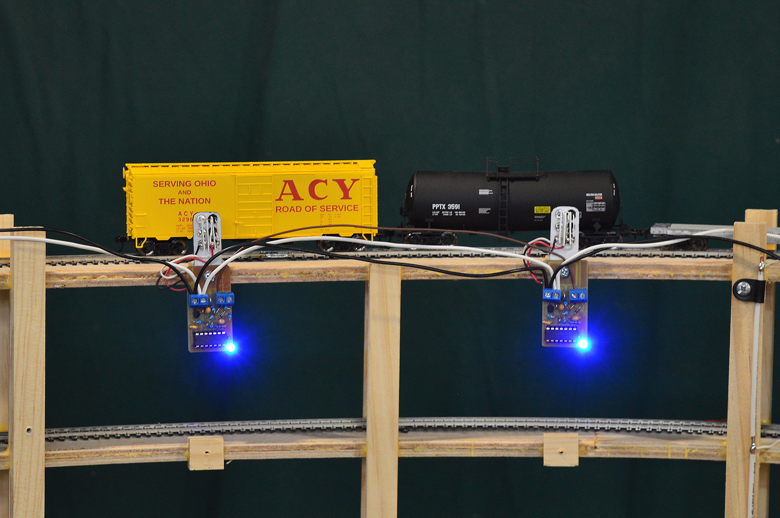
The individual board solution looks like a winner. Works great. Satisfied it will work I began mass production and installation. I tested each sensor as I mounted them. 12 units (6 master, 6 slave) are installed so far.
The wiring now follows the roadbed and can be affixed nice and neat once all the wiring is completed.
The workbench is setup for production, a bunch of boards are etched and ready for cut and drill, and there is a brand new tip on the soldering iron. Ready to crank out sensor circuits.
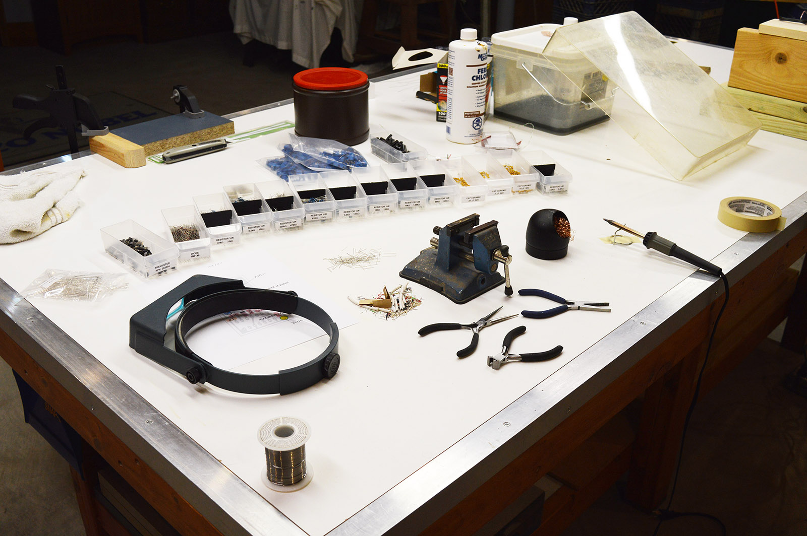

See ya 120 circuit boards from now!

More awesome work, Alan… I was wondering how you were getting along…good to hear from you! Carry on! Excellent, inspiring work, as usual! Clark
Thanks Clark. Sorry I have been neglecting the blog lately. I’ll try to be more timely.