Over the past two weeks I have been pointn’-n-clickn’ my way to a prototype for the fascia panels. My mate from down under, Jason Miller of JL&T fame, has kindly provided input as the design evolved. I think we may have a design ready for a test build.
My desire is to maintain the style of the power panels with the oak frame 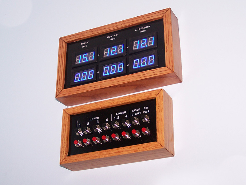 and black face. Due to the complexity of the fascia panel graphics it is not practical to build with the same technique used on the power panel faces – black painted rear, rub-on dry transfers, and several applications of flat sanded clear coat. It would be a nightmare to do all the fascia panels with rub-on dry transfer lines and I seriously doubt I can do a presentable job of it. No, it is time to switch gears.
Enter the photo quality inkjet print. I am well versed with Adobe Illustrator so the allure of using a drawing program to make the panels is too much to resist. The beauty of vector drawings is the final printed product will be razor sharp. There is no raster (JPEG) fuzz on the edge of lines. Printing on quality photo paper will further add to the appearance.
One unbreakable constraint for panel construction is overall height. I do not want panels that hang below the fascia thus distracting from the view of the lower deck, or panels that extend above the upper deck scenery. That means the panels can be no more than 6-1/2″ tall outside dimension – 3-1/2″ benchwork + 2″ foam + 1″ fascia bottom lip. The oak frame is 1/2″ stock so an inch is lost. Add a little inside margin and I am left with a usable panel face height of about 5″. Not a lot of space to work with.
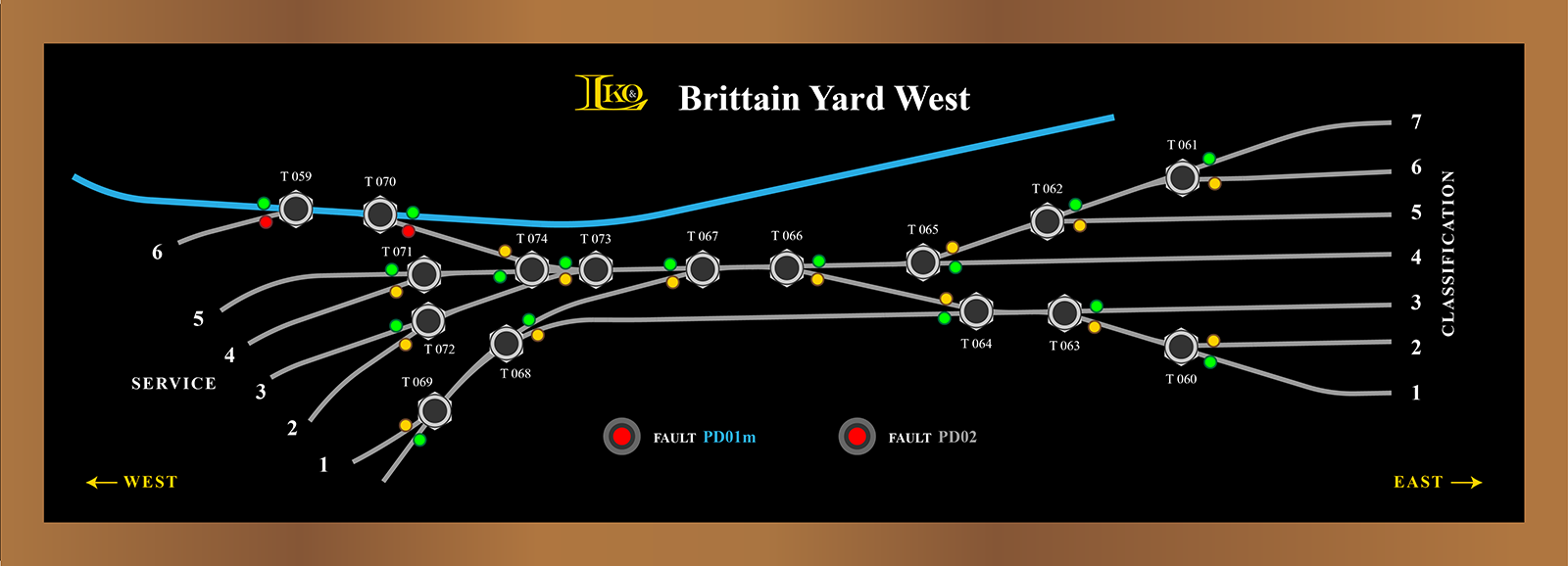
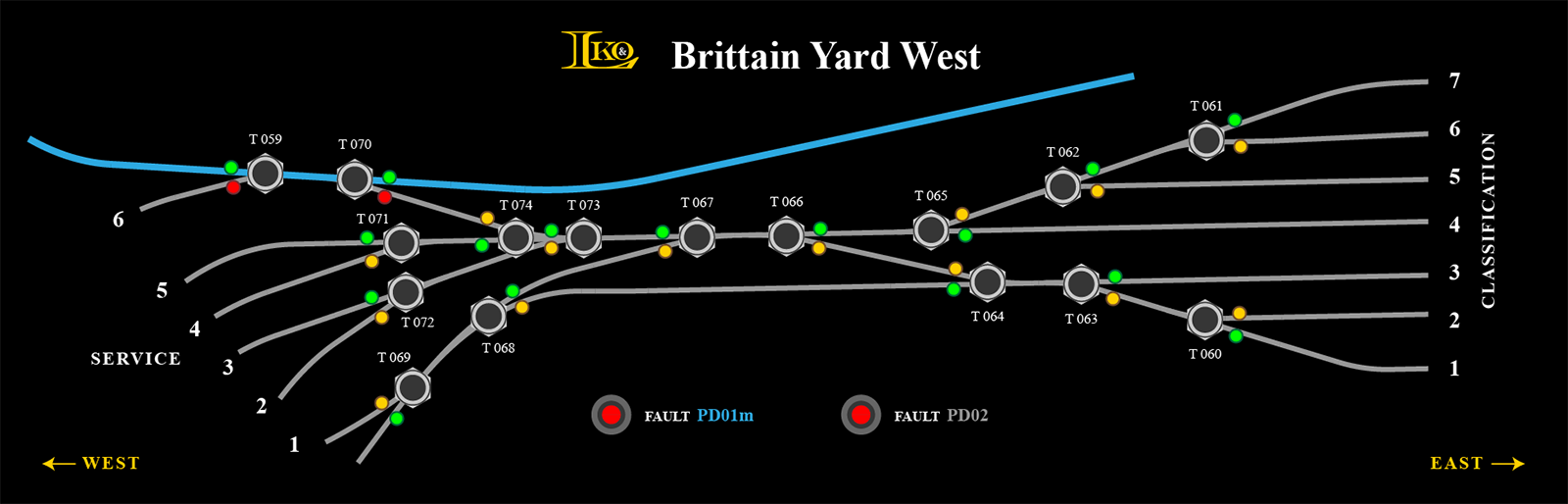
Using the west end of Brittain Yard for the initial go at it, here is my prototype fascia panel design. Everything on the drawing is to scale for a 6-1/2″ x 18″ panel.
Getting From There to Here
I had originally planned on using 5mm bi-color LEDs in panel bezels. My initial designs reflected such. The problem was in the amount of information presented to the operator. The LED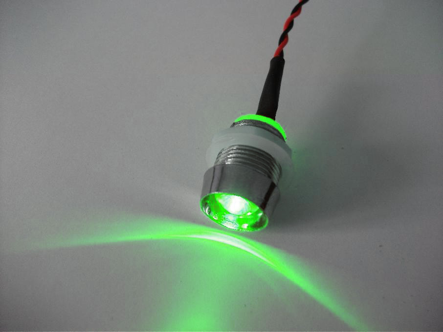
 color indicated if the turnout was in the normal or reversed position as you would expect. Typically, the diverging route is the reversed position so no further information was needed. But what if the diverging route was the normal setting and the through route was the reversed? I don’t think a real railroad would do that but on a space compressed model railroad who knows. It could happen. My intent is not so much doing things the way real railroads do but rather on making my railroad operate well. That means we need more information at the panel.
Adding colored lines to the design yielded the necessary information but made the panel cluttered. It also forced relocation of the push button switches away from the turnouts because there wasn’t sufficient space for everything. This in turn necessitated a lettering scheme to correlate switch to turnout. Not good as can be seen below.
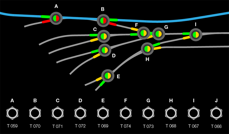
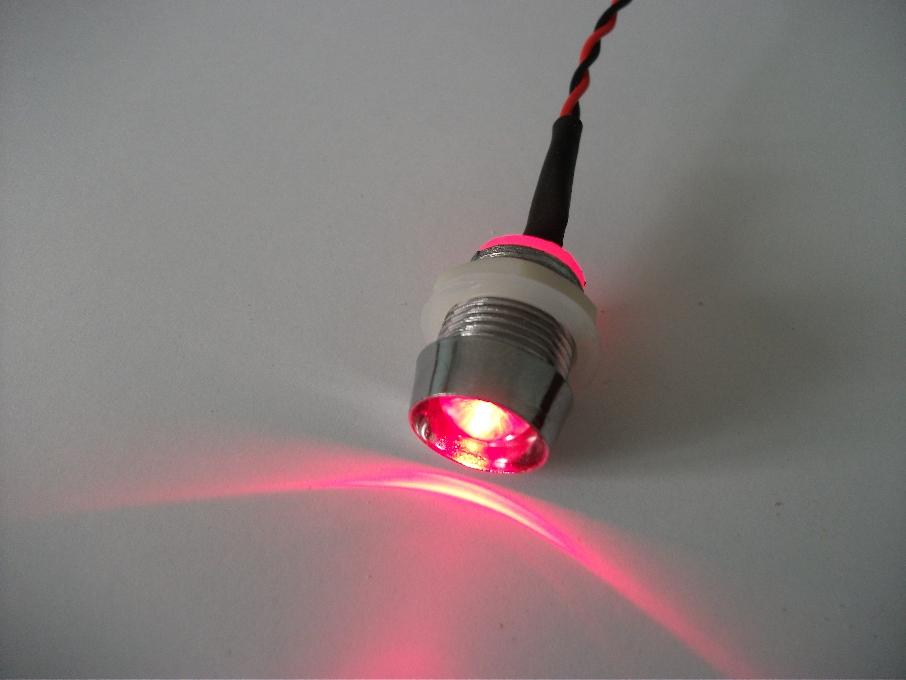
Jason suggested I ditch the 5mm LEDs and fancy bezels, which I had focused on because I have them on hand, and in their place use pairs of 3mm single color LEDs. That turned out to be a winning idea. It freed space for the push buttons and removed the need for colored lines. So I have to buy a few hundred more LEDs, no big deal. China products via eBay are so ridiculously inexpensive it won’t hurt the wallet. Placing the 3mm pairs in bezels brought back the overcrowding problem so LED bezels were eliminated altogether except on the power district fault indicators. A downside of the no-bezel approach is nothing to dress up the acrylic face drills. I’ll have to be very careful while drilling so every hole comes out clean and pretty. I’ve cut and drilled a lot of acrylic sheet over the years. I can pull this off.
The Goal
Functional, attractive panel faces in a small space!
Construction
Graphics complete it was time to figure out how to physically construct the face panel. The considerations:
- Cannot use any adhesive on backside of acrylic face – it would be visible
- Print needs held tightly to the acrylic face across its entirety – good appearance
- Print must fit tightly around drilled holes – create a full black face, no voids
- LEDs need to be soldered to a PCB – prevent a rats nest of point-to-point wiring
- LEDs need uniform fitment to acrylic face – can’t have some high some low
Here is what I came up with:
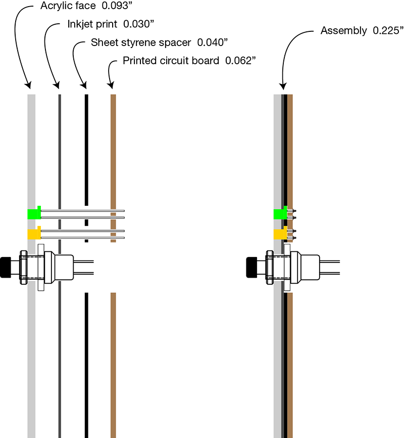
A sandwich of acrylic sheet, photo paper, polystyrene sheet, and copper clad circuit board fitted with push button switches and flat top LEDs meets the requirements. Each layer will have the appropriate diameter holes drilled. Photo paper with 3mm LED holes and 0.375″ switch holes for a nice tight fit around components. The polystyrene sheet, necessary to account for the LED flange thickness, will have corresponding drills except the LED holes will be 4mm, offset to accept the LED flange orientation, and the switch holes will be 9/16″ to clear the backup washer. Finally, the PCB drilled for the LED leads and 9/16″ holes to clear the switch backup washer. Assembled, the sandwich is 0.225″ thick which sounds to me like a very nice fit in a quarter inch router slot in the oak frame. At a quarter of an inch thick with a PCB on the back it should be very stiff so I don’t anticipate any panel deflection when a button is pressed. As good fortune would have it, the thickness of the acrylic and photo print combined is 0.014″ shy of the LED height above flange meaning the LEDs will just barely protrude from the panel face. That is just enough so as not to expose the drill edge. Couldn’t have asked for better.
OK, you are probably thinking…
“Yeah, right. Like you 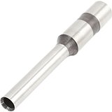 can get all those drilled holes to line up exactly with each other.”
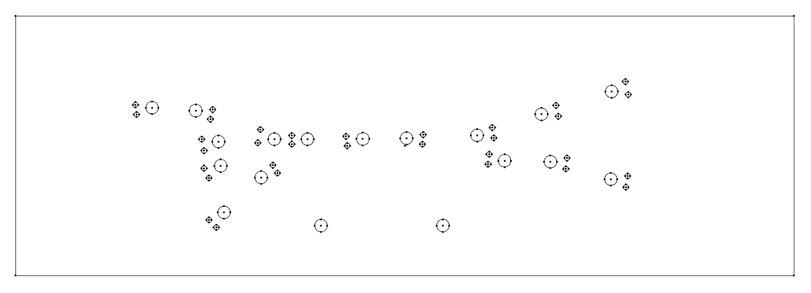
Yes, I believe I can. Adobe Illustrator to the rescue! It allows me to print templates with registration marks that have only cross hair drill points on them. Just like an offset printing press, I align the registration marks on each piece and drill in the drill press. For the inkjet print I will use paper drills. Everything else can be drilled with regular twist bits. Should work, don’t you think? I’m certainly going to give it a whirl.
Pieces Parts

I have a couple suggestions for you if you don’t mind some advise. Lexan (polycarbonate) is much more forgiving to drill than acrylic and is just as durable. it can also be cut with out chipping on a table saw. A trick i learned after trying to drill the holes on each seperate layer was to sandwich it all together and clamp it and then drill holes thru the lexan (i use two sheets of 0.093″ lexan with the artwork in between). This makes the holes line up perfectly. I replace the artwork after drilling with a fresh copy as the twist drills tend to tear up the paper.
I leave the plastic coating on the outside faces of the lexan but remove it from the faces that touch the artwork.this keeps the faces protected until it is time to install them.
If you have access to a laser printer or a copy machine i would highly recommend you print it on one of those. The toner actually fuses to the paper and doesn’t run if it ever encounters any form of moisture. Inkjet ink will run when subjected to moisture.
If you can find them, flat faced LED’s do exist and that is what I use on my panels. This makes the LED’s flush with the front face of the panel. i found some on Allelectronics a few years back and bought about 1000 of them and i still have a bunch.
I install the push buttons first which holds all the layers together. i then insert the LED’s and super glue them to the back of the panel.
Here is an example of my panels. http://www.coloradofrontrangerr.com/construction/block-detection-and-signaling/control-panels
I hope this info helps!
Chuck,
Thank you for the informative comment.
I have no experience machining polycarbonate. I know it is one strong plastic. Safety glasses material. Perhaps I’ll pickup a small piece and experiment. Thanks for the tip.
Not so much worried about moisture on the print. The face sandwich will be totally encapsulated in the oak frame.
The LEDs I am using are the flat top variety.
I can’t drill the entire sandwich at one time because the hole centers are not the same. The LEDs have an offset flange and the PCB is drilled for LED lead spacing.
Looked at your panels. Very nice. Well done.
i got my lexan from either lowes or home Depot. my panels are a standard size thruout the layout which is 8″ wide by 3″ tall.
I use normal twist drills ( brand new sharp ones) to drill the holes using a drill press. i have made 12 panels and none of them have cracked or chipped while drilling.
THe PCB will certainly make wiring easier and cleaner. Your wiring has been most impressive and is very well thought out and done. you wouldnt happen to be an EE would you?
I did switch to a higher quality white capped pushbutton. the cheapie red ones kept snapping off even with minimal use.
I will keep watching your progress on the layout!
Hi Alan
I really enjoyed this article. I am preparing something similar, but not there yet. So I am looking forward to your update and see how it all goes 🙂
Good luck.
Reg
Glynn
“you wouldnt happen to be an EE would you?”
ha! No, I am most definitely not an electrical engineer. The number of ICs that I have released the factory sealed smoke from is proof of that! 🙂
Brad point bits like these:.http://leevalley.com/us/wood/page.aspx?p=42247&cat=1,180,42240
might be worth a try for a no chip entry and clean edges. And the brad point makes accurate drilling much easier than standard twist drill bits.
David,
Check out these bits: http://www.carbideprocessors.com/drill-bits/plexi-point-drills/
and they have 3mm! : http://www.carbideprocessors.com/plexi-point-drill-3mm-dia-vortex-14400118/
Sweet!
Ain’t it great when you can find the exact tool for the job instead of having to futz, putz and pray.
Looking forward to seeing the finished product.
When drilling does placing masking tape on the acrylic help with keeping the holes clean?
Yes somewhat. Chips, if they are going to occur, will usually blow out masking tape or the backing sheet that comes on the plastic. I have very good luck sandwiching the finish piece between two scrap pieces of plastic. Makes for a bit of waste but does a good job preventing chip out.
Alan we drilled a panel for things like that after an over lay was applied for the new n scale panel under construction at my club. We also laminated diagrams to both sides that were printed on vinyl.
If you want to see the panel which is not as sophisticated as yours,
http://model-railroad-hobbyist.com/node/18644?page=34
[…] project is the control panels. The design is on this post. They will take a while to build but should be fun. Once built and located, the fascia will be […]
[…] control panel faces I saw polycarbonate which reminded me of a comment by Chuck Lee on this earlier post. So I included polycarbonate as I drilled down in the search results to the 0.118″ thickness […]