In the previous post I promised a movie of the hill brakes in action. Before making the movie I wanted to add some sort of protection so an engineer doesn’t accidentally hit the brake pin protruding up between the rails. With an idea in mind I set out to build a prototype. Two months on, experimenting with seemingly countless variations I still don’t have anything that impresses me. To paraphrase Thomas Edison, “I have not failed. I’ve just found a dozen ways that won’t work.” So, I ask for your further patience on the movie. PS. I have laser diodes on order. This is getting out of hand!
The helix application
Meanwhile, I have begun work on the south helix. This is the helix under the Brittain engine service area.

The interesting thing about the helix placement is its incorporation into the upper deck. Three quarters of the uppermost loop around the helix extends above deck zero elevation (train height).
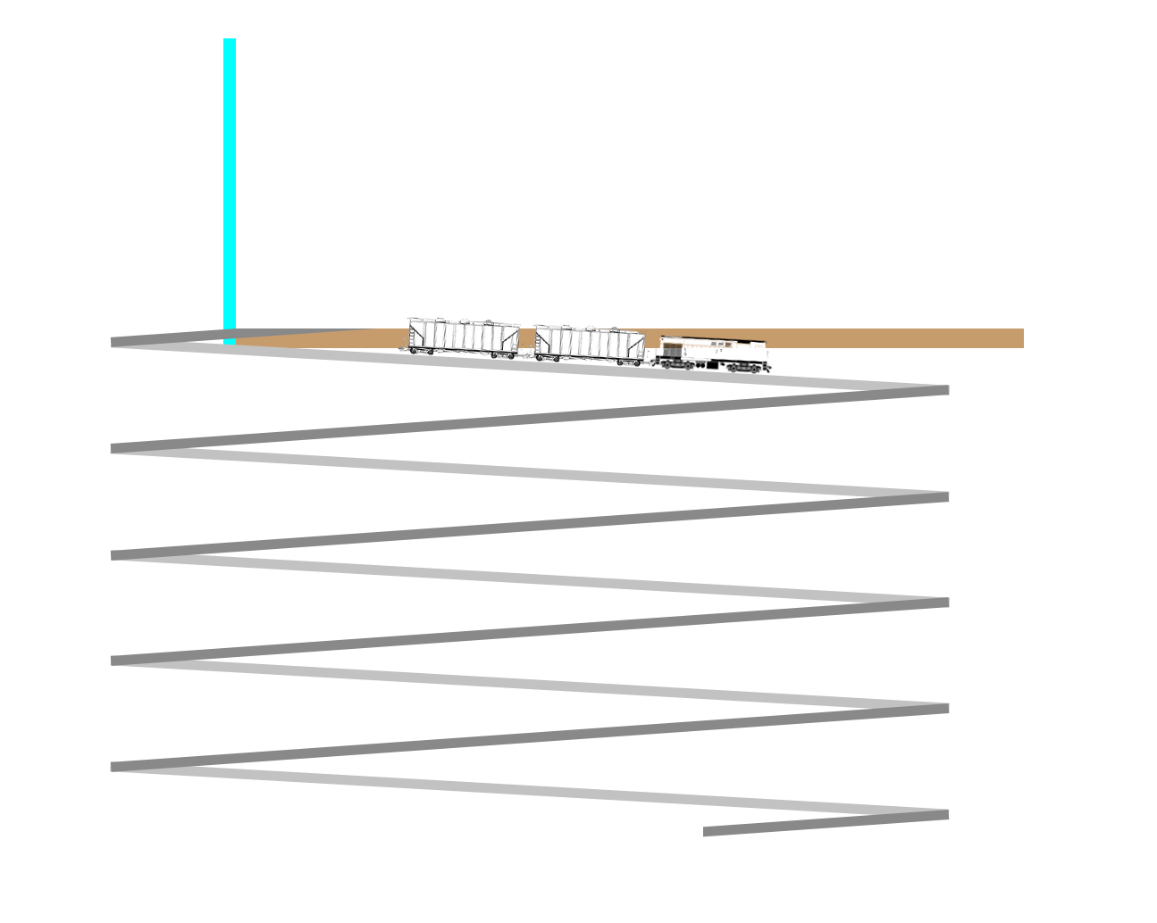
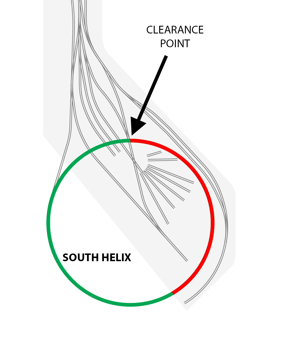
The part of the helix top loop that will extend above zero elevation (train height) and not be behind the backdrop is shown below in red. The key to making this work is a 3-1/4″ separation (NMRA gauge) at the clearance point. The red portion will be hidden from view by some creative terrain, retaining walls, and other assorted disguises.
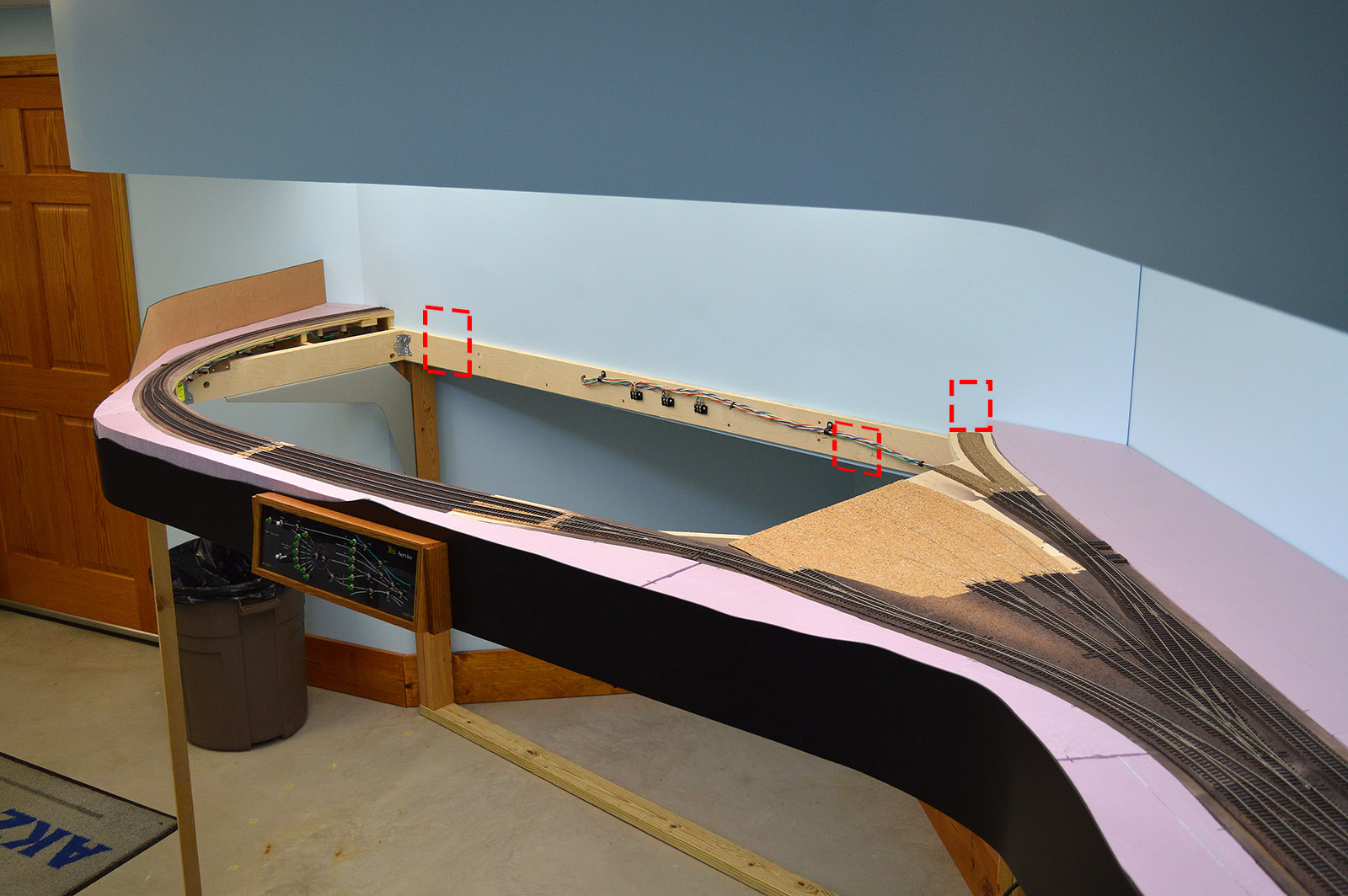
The helix supports the engine service module that will sit above it. The very reason I built the benchwork with no crossmembers in the helix area and why the engine service module has yet to be built. The dotted lines in the picture below indicate where cutouts will be required. I am not going to actually make the cutouts until I get the helix built and in position. The existing benchwork board that runs along the bottom of the backdrop in the picture is not structural across the span. I can hack holes in it without worry.
Design
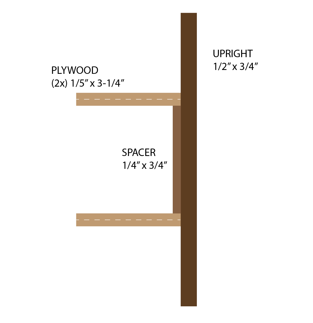
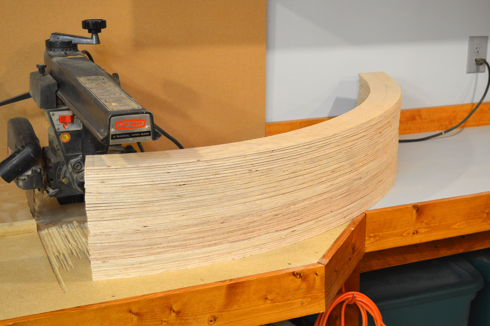
Of the many methods of building a helix, I chose plywood roadbed with wood uprights sitting on a single rail frame. The plywood is common 1/5″ (6mm) underlayment used on floors. It has a nice surface finish and is relatively inexpensive. Available in 4’x8′ sheets at Home Depot. I am going to stagger laminate the pieces with wood glue to give a final roadbed thickness of just under 1/2″. Staggering the pieces will consume a lot of glue but it eliminates biscuit joining thin plywood. The uprights will be 1/2″x3/4″ square edge trim pine with 1/4″x3/4″ screen door trim spacers glued between roadbed layers. The spacers will be angle cut to match the grade so they are vertically plumb.
The original XTrakCAD file showed a 32″ nominal radius helix would fit in the available space. To validate this I dropped a plumb off of the existing benchwork and roadbed marking the position on the floor. Then by trial and err I moved around a taped on center point until I found the maximum radius circle that fit inside the marks and walls. Turned out to be 35-1/2″ radius. Enough to fit a 32″+ track centerline radius helix. Bravo XTrackCAD! My crude surveying setup:

As I do with most of my construction, I started with a 1:1 scale Illustrator file. This method makes sure what I have in my head will actually work in real life. Plus, it gives me super accurate measurements. Far more accurate than my saw cutting accuracy in fact.

The scale illustration allowed me to accurately calculate the grade for the top loop from exit point to clearance point. It is ~2% (3-1/4″ rise over 154-7/8″ run). Slightly steeper than the 1.8% grade (3-3/4″ rise over 206-1/2″ run) of the four loops below the benchwork. Using the 28R method the curve compensated grades are 2.8% and 2.6% respectively.
I wanted the roadbed to be the minimum width necessary to allow a 12″ (actual), 87′ (HO) locomotive or car to traverse the helix without the overhang/underhang striking the uprights. With a centerline radius of 32-7/8″ that turned out to be a roadbed width of 3-1/4″.

Frame
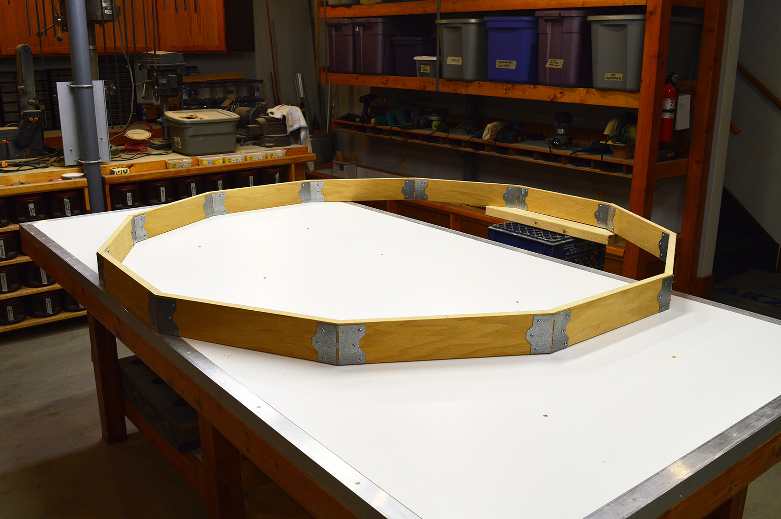
The helix frame follows the same construction method used in my benchwork – 3/4″ x 3-1/2″ ripped plywood joined with skewable nailing plates. In actuality, I had to use 3/4″ hardwood faced MDF for the segments since I am working from what I have on hand. The dimensions of the partial sheet of MDF were just perfect for the segments I needed. The segments were ripped and then cut to length with a 15 degree angle on each end. The nailing plates were bent to 30 degrees. Finally, the pieces were assembled into a big dodecagon.
Abutments
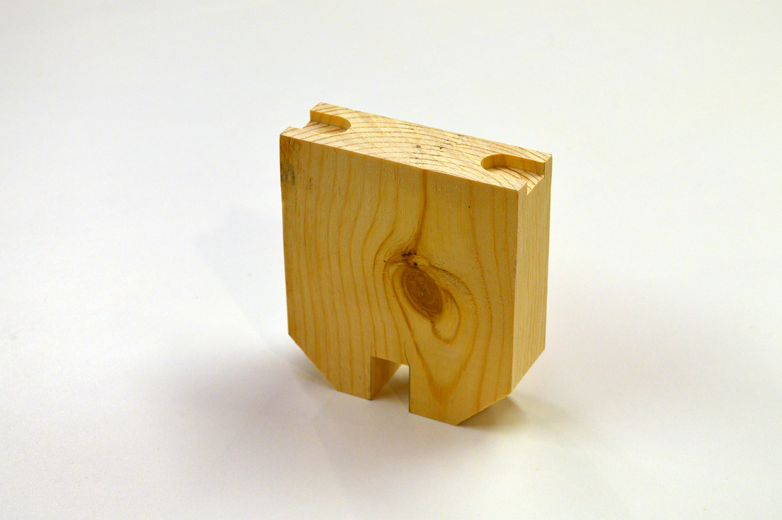
As the foundation for the uprights and to set the grade I cut to size 12 abutments using the table saw. The raw material was 2x6s from the cutoff bin. The dimensions were dictated by the Illustrator drawing. Each abutment was cut at a 1 degree angle on the top to match the grade. To make level and square mounting points for the uprights I used the router table with a 3/4″ straight cut bit to cut notches. The same 3/4″ bit cut the bottom groove that fits over the frame segment. As a finishing touch I cut the bottom corners 45 degrees. Hopefully that will prevent me from being jabbed by a corner when I am working inside the helix.

Roadbed
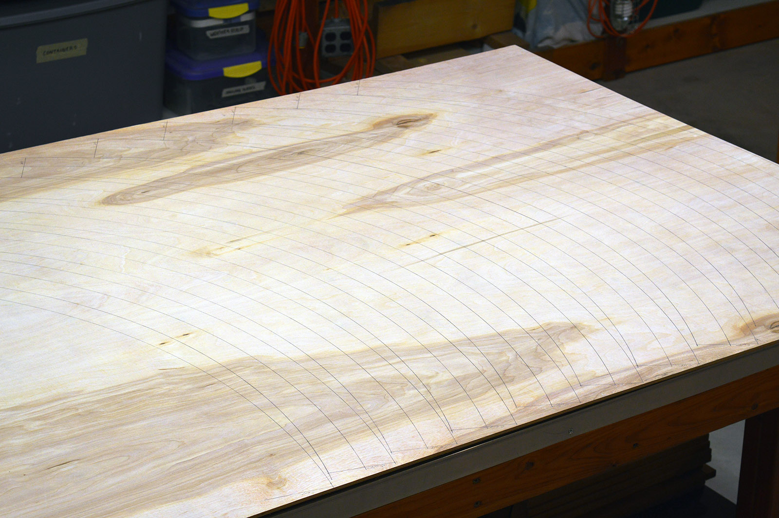
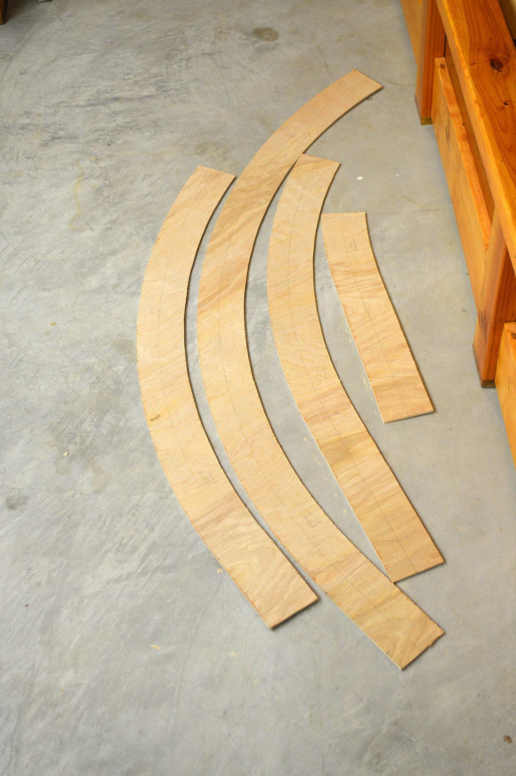
Cutting semicircles from a rectangular sheet is usually very wasteful. I tried my best to minimize that waste by individually arranging the cuts one at a time. Again, another high tech solution was employed – a nail and a yardstick!

A little time consuming but with nice benefits. I reduced wood waste and have a nice centerline mark for laying track. The track centerline is especially important. The underhang of a long loco or car is greater than the overhang. Therefore, the centerline is not actually in the center of the roadbed. It is offset to the outside of the curve. I guess you could call it an uncentered centerline. That makes it just a line, huh?

Next up was a few hours spent with the jigsaw resulting in 44 segments and a whole lot of sawdust!
The upper and lower exit segments included a 12″ straight extension that will eventually be tied to the existing layout. It really messes with your mind trying to keep track of upper/lower laminate positions since the segments will be offset 50% from each other.
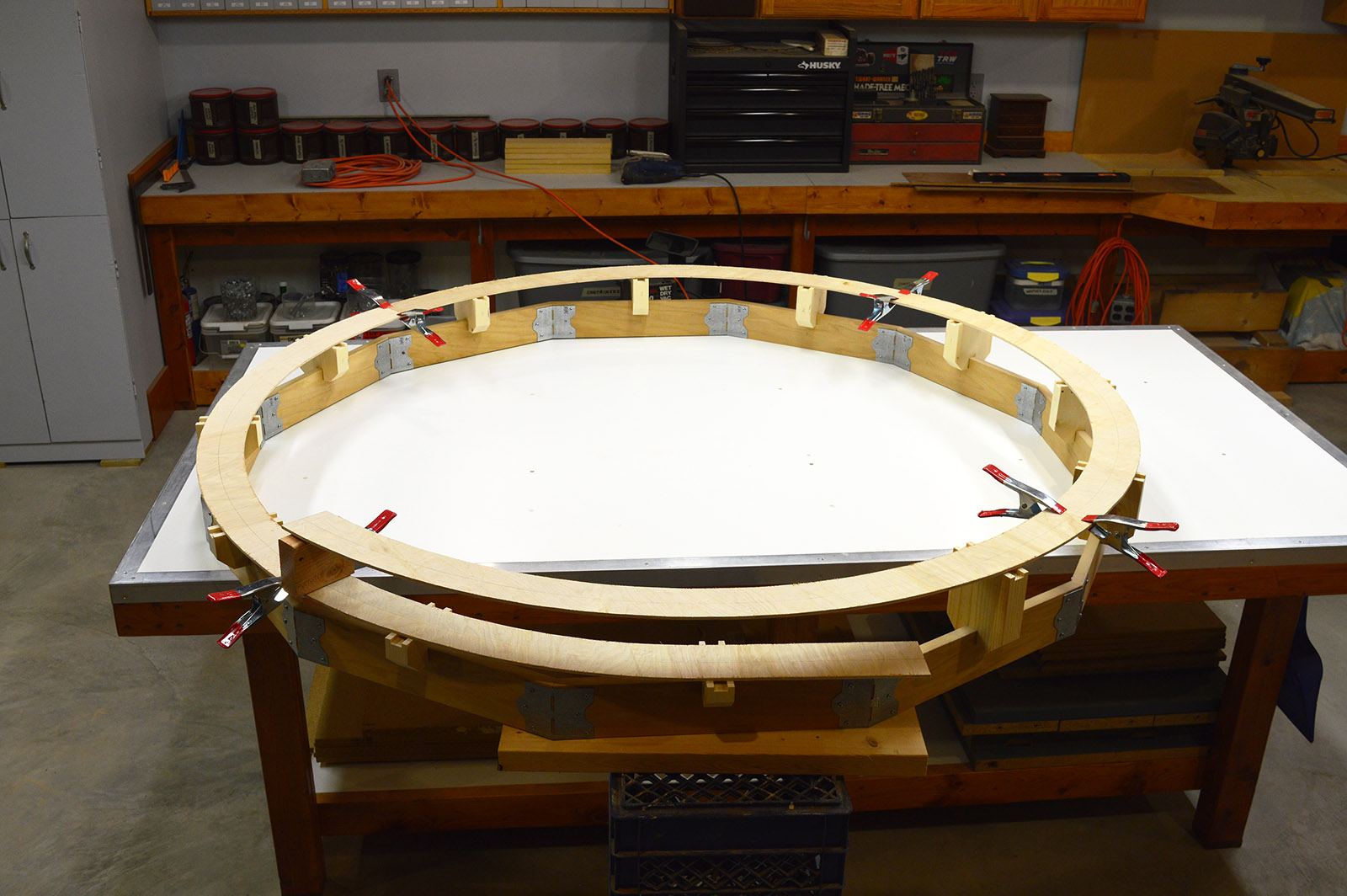
Test fit up
Before breaking out the glue bottle I thought it best to do a test fit just to make sure it all fits together. Looks like we are go for assembly.
Temporary spacers
The uprights won’t be installed until after all of the roadbed and track is complete. During assembly I’ll use temporary spacer blocks that are vertically sized to sit on the track. Made a bunch from scrap wood.

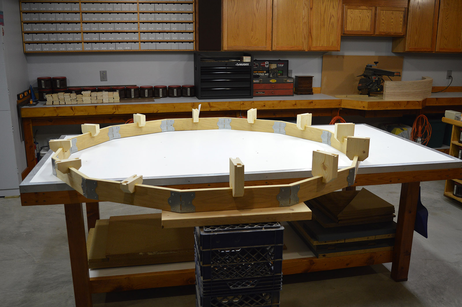
Assembly
Abutments glued in place and ready for installation of roadbed and track. See ya next post!

Wow. Impressive design. I like how you used Illustrator.
Thanks Greg
The thought process that goes into your designs
& solutions is astonishing!
And the fact you used “ dodecagon”…!🙌🏻
Well done again, Alan…👍🏻