Success! The fascia panel wiring is done. Well, all that can be completed at this time anyway. So, let’s say 95% done shall we?
Some of the fascia panels have controls for things that have yet to be built. This fact is especially true on the Brittain Service panel. There isn’t much to wire the panel to! Construction of the Brittain Service track module hasn’t begun. Elsewhere there are crossing gate defeats, brakes, doors, gates, and even a working coal tipple for which controls exist on fascia panels but no appliances are on the layout at this time. Planning for the future I guess you could call it. Nonetheless, I can now say the controls and indicators for every currently installed upper deck turnout and power district circuit breaker are wired and working properly. Hurrah. Following is a brief explanation of how I went about making my panels functional.
The fascia panel wiring utilizes four different style harnesses depending upon the situation:
- Fascia panel to track module (all, except below exceptions)
- Fascia panel to two different track modules (Spur 4, Market St.)
- Two fascia panels to a single track module (East Akron 1 & 2)
- Fascia panel to fascia panel interconnect
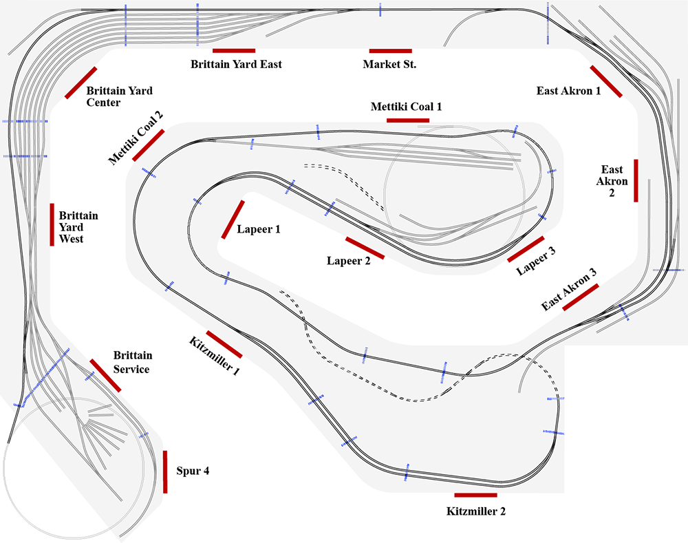
Each fascia panel has a corresponding track module, the module containing turnout(s) located directly in front of the panel. The track module boundaries were determined by physical constraints during construction and to allow easy installation/removal. The fascia panels were located so as to facilitate operation i.e. where is the operator most likely to stand. Panels are shown in red, track module boundaries are shown as dotted blue lines.
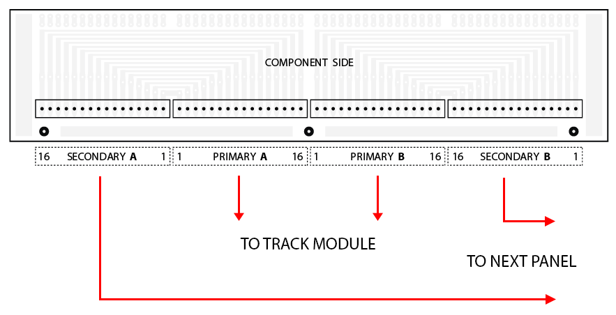
Each track module wiring harness is connected to its respective fascia panel via the Primary A and Primary B connectors on the panel rear. This arrangement supports up to 32 separate electrical circuits and is the most common on the layout.
More complex fascia panels have two sets of connection boards with the additional connectors labeled C & D for a total of 64 electrical circuits.
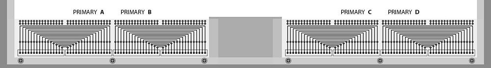
Brittain Service is the odd man out as it has a unique 96 circuit connector arrangement necessitated by the sheer number of controls on a single panel. More on that later.
On fascia panels that connect to two track modules (Spur 4 & Market St.), where possible, each track module is constrained to the same connector. Track module 1 uses Primary A while track module 2 uses Primary B. Where it was not possible to keep the harnesses constrained to separate connectors, JST SH style connectors were inserted inline in the harness. Had this not been done then the two track modules would be forever linked together by the wiring harness making track module removal virtually impossible. Incidentally, Spur 4 violates this separate connector arrangement due to a stupid design error on my part. I inserted inline connectors into the Spur 4 harness. There, mistake corrected.
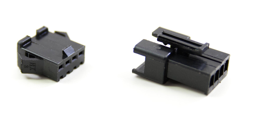
The same JST SH style connectors were also used in some of the East Akron 1 and East Akron 2 panel wiring where two panels are connected to the same track module. Not out of necessity, rather, to avoid removing a long wiring harness when the track module is removed. Really just a convenience addition.
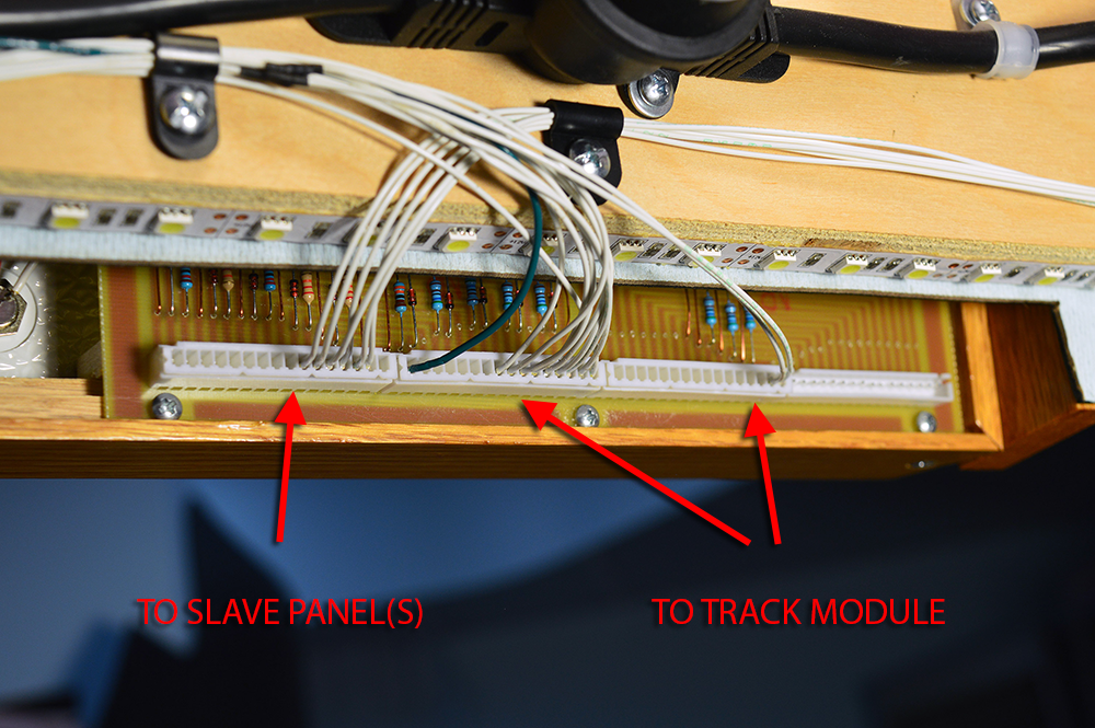
The final wiring step was panel-to-panel interconnects. These are the harnesses that run along the front underside of the benchwork. Many turnouts can be operated from more than one panel and many of the power district fault indicators and other appliance controls appear on more than one panel. Having multiple wire copies in every track module harness each going to different fascia panels would have been a spaghetti nightmare not to mention using a lot more wire. So, the fascia panels use a master/slave arrangement. Any given track module wire harness connects only to a single fascia panel. That panel becomes the master for that particular track module. If duplicate controls on other panels are utilized then the panels are daisy chained together using the Secondary A, B, (C, D) connectors. The interconnected panels then become a slave to this particular master. A master panel can have as many slave panels as needed. Any one panel can be both a master and a slave at the same time. In fact, many panels on the layout are both a master and a slave to at least one other panel. This arrangement means there is but a single wire for any circuit in the track module harness for simplicity’s sake and it keeps the track module harnesses completely independent of the number of panels connected. Cool, huh?
There you have it. You know as much about how the fascia panels are wired as I do. Hopefully, that helps you make sense of this example photo.
If you are thinking “with all this talk of wiring where are all the pictures of wiring?” Good question. Don’t worry, there’s no shortage of pictures. I am going to use the next post to document each of the panels. It will be picture laden. If this post hasn’t given you a headache the next one surely will. 🙂

I like your explanation and pictures. I have been in “a fog” trying to find the best description – particularly one that explains it “like it is.” Thank you for posting and I look forward to your future post.
Congratulations Alan…!
Massive effort, love the connectivity of the modules, I’d need a week just to go over, and look underneath your layout…