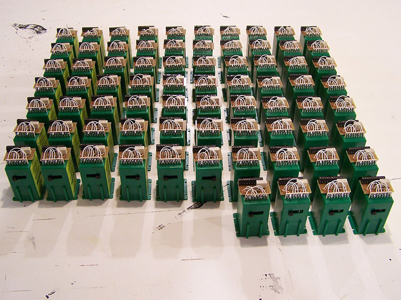
A few thousand solder joints later I have assembled enough Tortoises for the entire layout. 74 to be exact. 72 for the layout and two spares. While you would think it was monotonous it really wasn’t. In fact, I quite enjoyed assembling them. The very first one took well over an hour. The following few units required about 45 minutes. By the time I hit unit 30 or so I had it down to less than 15 minutes! I almost believe I can assemble one blindfolded now.
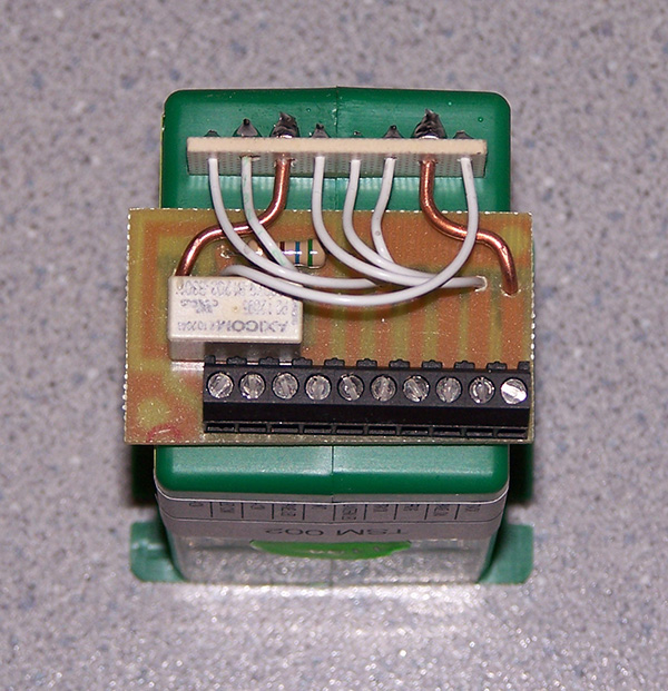
The only tricky part is the bending of the 14 gauge wires that mount the circuit board to the Tortoise. They have be just right so they line up with their corresponding holes in the Tortoise electrical connector and at the same time position the board centered and level on the Tortoise plastic housing. Functionally, it doesn’t matter what position the circuit board is in. It’s the perfectionist part of me that simply had to have them centered and level.
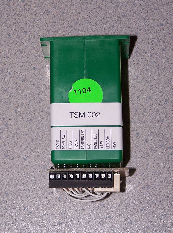
With some Avery 8167 labels printed and applied the Tortoise inventory is ready for installation.
