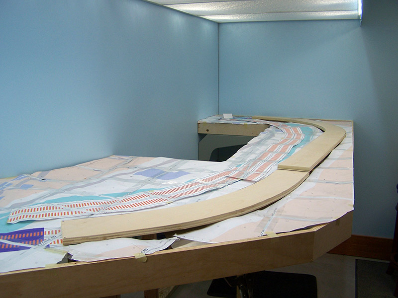
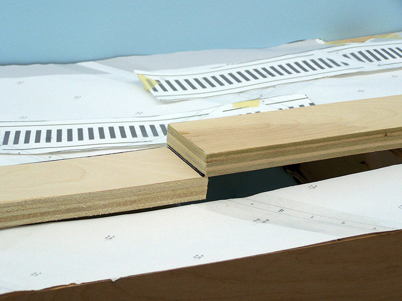
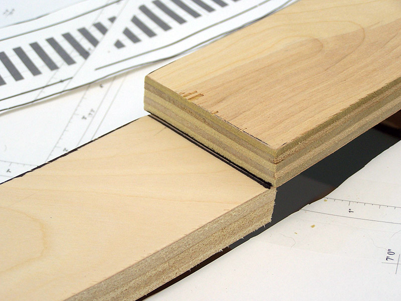
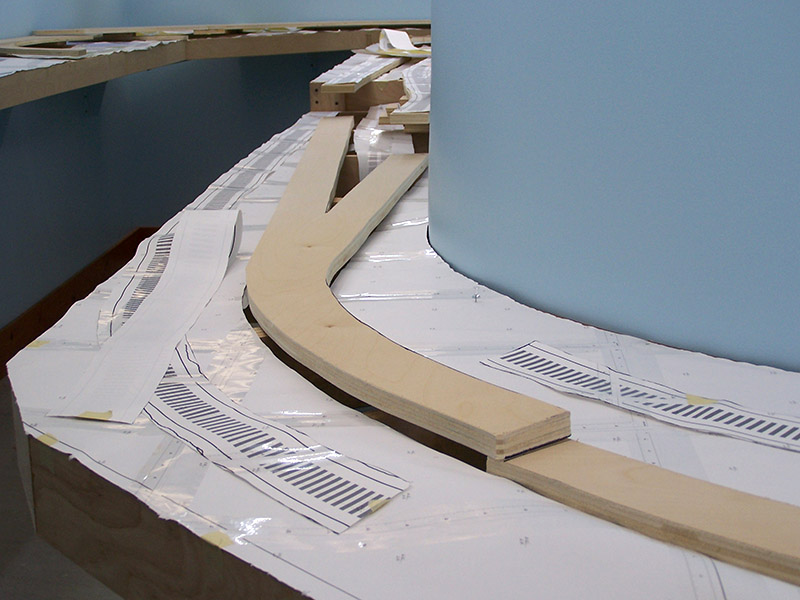
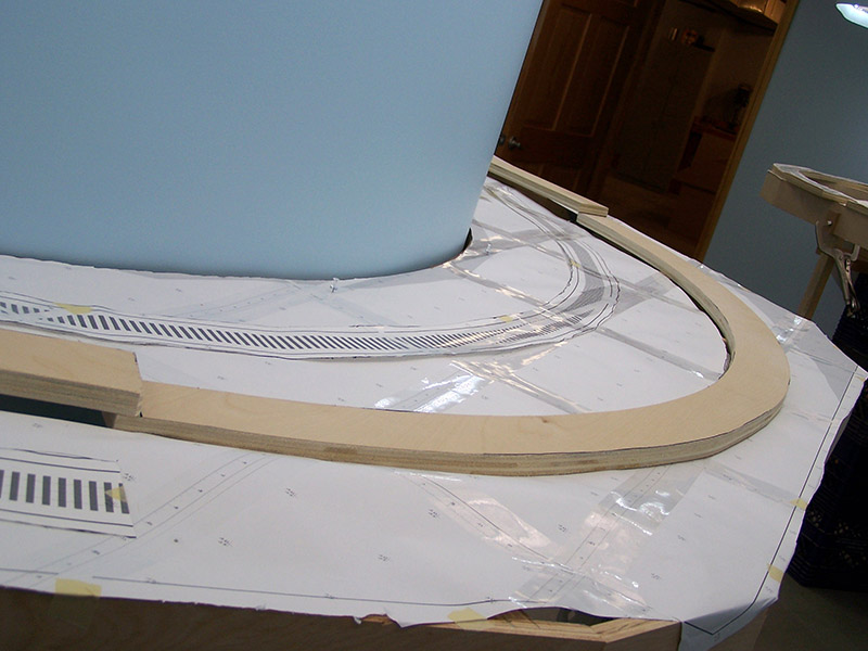
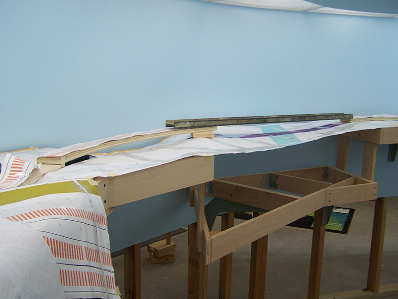
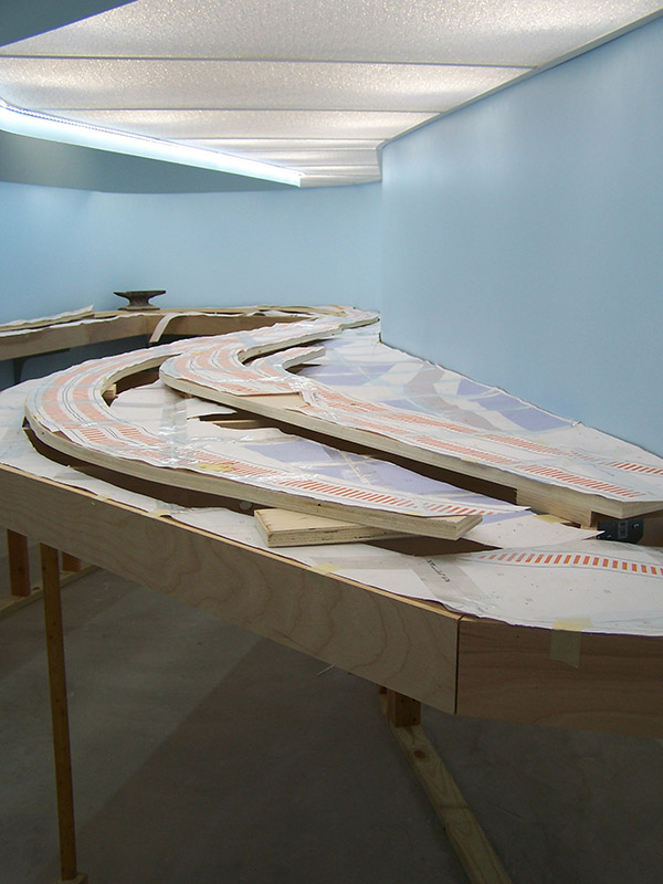
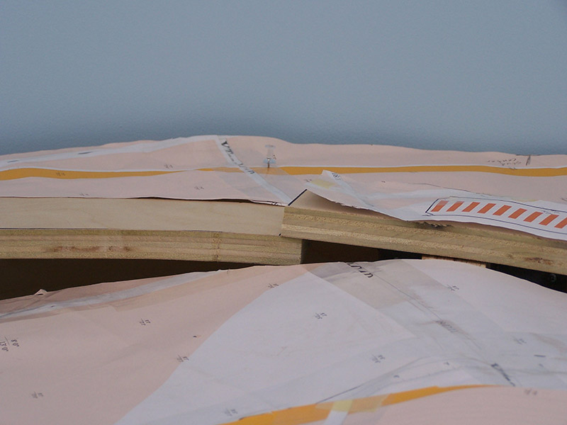
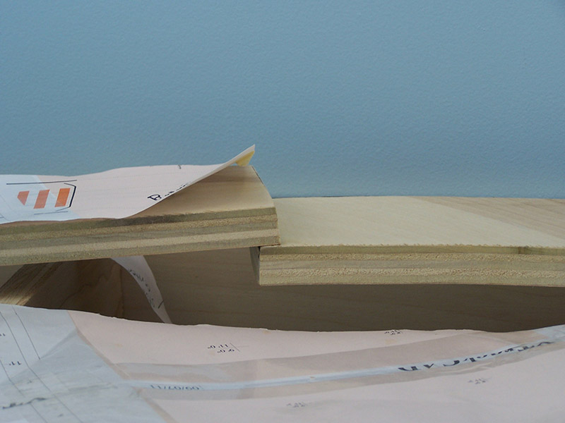
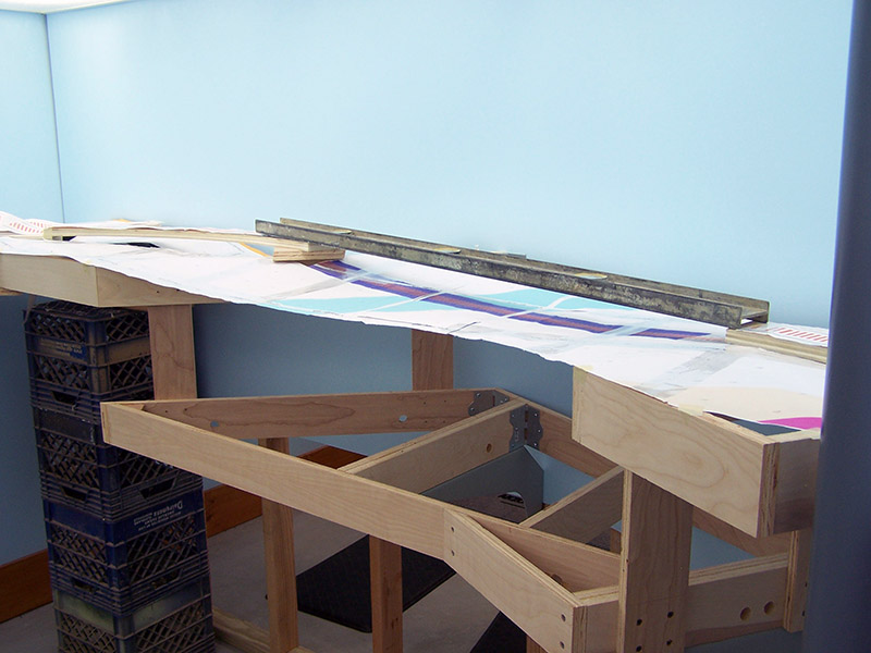
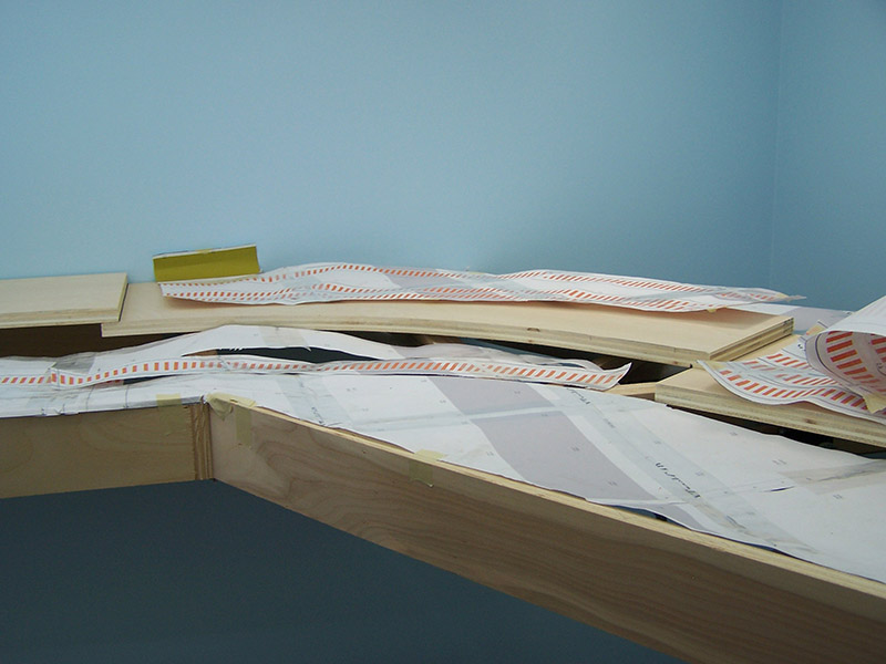
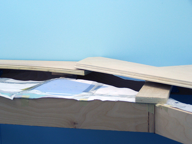
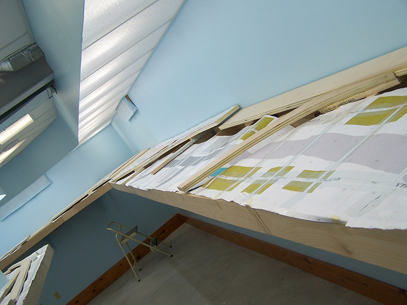
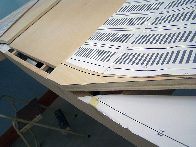
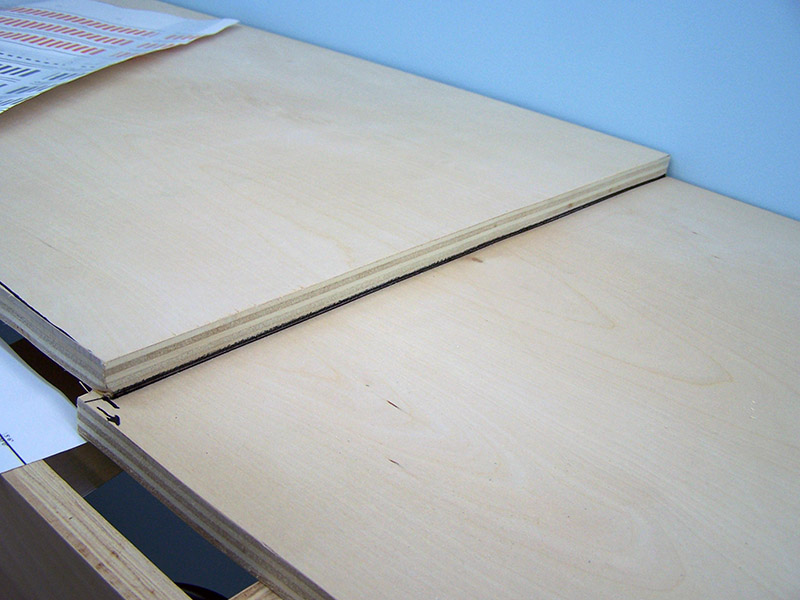
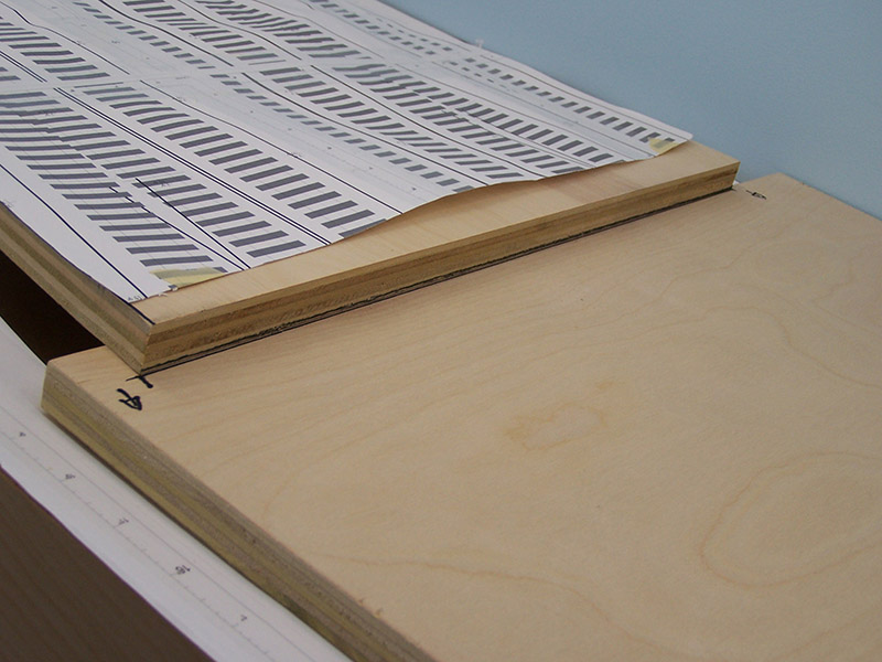
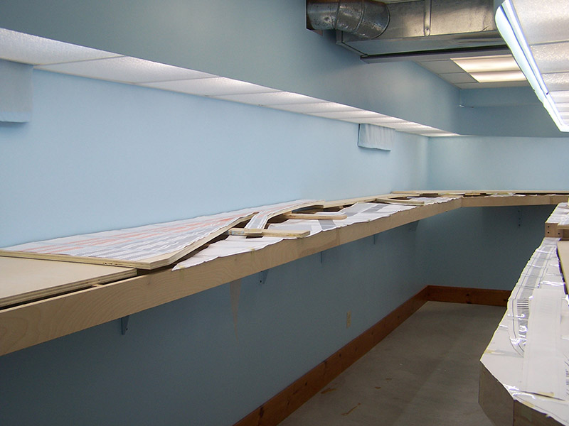
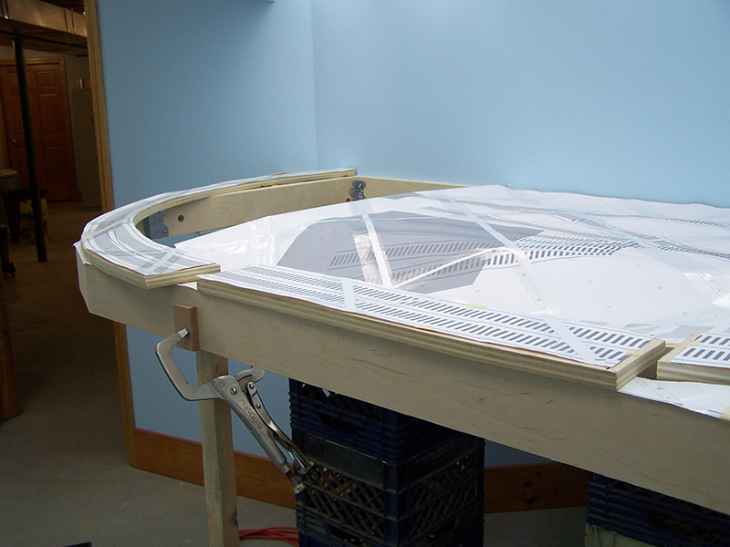
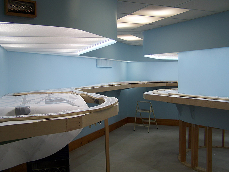
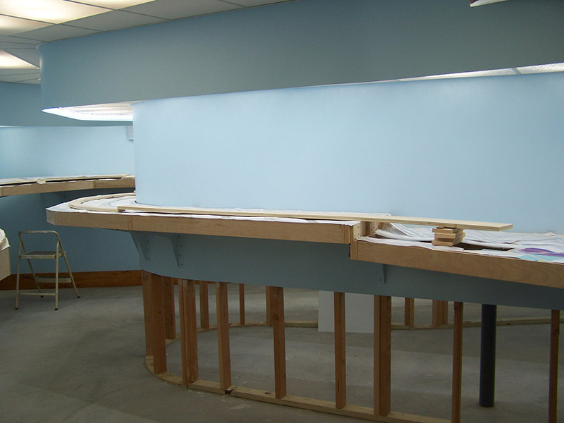
There is a follow-up to this post that describes further refinements made to the Tortoise control. View it here.
While I cut the final pieces of sub-roadbed I am thinking through the next phase to come – track laying. For regular readers of the LK&O blog you know the plan is to build each track “section” on the workbench for transfer to the benchwork once complete. Think of it as trackwork modules. Each module will be entirely complete before being placed on the layout. This means all electrical and mechanical components must be mounted and working.
I am requesting your input, please.
Starting with the very first section I will need to mount and make functional the Tortoise turnout machines. I want them controlled with the same pt# momentary contact push button switches I used for the lighting setup. They will be fascia panel mounted with multiple panel/switches for the same turnout in some instances. The fascia panels will have a track diagram with green/yellow LED position indicators. Nothing revolutionary there, huh? I should mention, there is no desire for DCC or computer control of the turnouts.
I am going to breadboard the schematic I found on the Internet (below) to make sure it performs as expected. Although I don’t totally understand them, I have had great luck building circuits taken from my old copy of CMOS Cookbook (now very tattered and torn from use). I know there is likely many circuit ways to go about this but I tend to favor CMOS because the circuits always seem to work even with my very limited understanding.
In addition to being CMOS, the feature that I really like about this circuit is the defined relay state during power up. This will allow the entire railroad to have a default power up turnout position. Parts from Digikey and circuit boards from Pad2Pad are within budget for this part of the railroad construction so cost is OK.
If you have electronics knowledge and/or a better way of controlling the Tortoises I invite you to comment. I don’t have to make a firm decision for a couple months or so. Thank you in advance.
— UPDATE #1–
More than one person on the modelers forums have suggested the circuit below. Thoughts?
— UPDATE #2–
There seems to be disagreement within the modeling community as to whether or not the 556 based circuit will power up in a defined state or not. Some say they have built the circuit and it does while others say it does only because of slight manufacturing differences in the component values. In other words, power up reset happens as a result of component choice/quality/tolerance/value/whatever instead of by circuit design. It is times like this it would handy to be an electrical engineer. 🙂
— UPDATE #3–
Don’t you just love it when you have an epiphany? Two of them back to back is just down right spectacular. That happened to me today.
Realization #1
Having a defined power up position of turnouts might not be such a good idea. What if a train, for whatever reason, is parked straddling a turnout? I may be setting myself up for a derailment as I turn on the railroad. Hmmm, maybe I had better not do that. Aborting the defined power up position of turnouts I set about rethinking the Tortoise control system.
Realization #2
Bistable dual coil latching relay. Tie one side of each coil to ground. Tie the other side of each coil to the contacts on one of the Tortoise’s SPDT switches. Supply V+ to the push button. Connect the push button to the center of the Tortoise SPDT. When the Tortoise moves it will change the push button from being connected to one of the latching relay coils to the other. The Tortoise will do the coil assignment. Pressing the button triggers whichever coil is presently connected. The relay moves in only 4ms. No way the Tortoise contacts will open faster than the relay actuates.
Is that simple and foolproof or what? No ICs, no circuit boards, nothing more than a switch and a relay. I am ecstatic!
Digikey pt# PB1085-ND $1.96 ea.
Digikey pt# EG2031-ND $1.32 ea.
Total per Tortoise $3.28
I’m putting away the breadboard. This is a done deal.
— UPDATE #4–
Schematic for the Tortoise control system. Ordered a single relay from Digikey so I can prototype the circuit just to make sure it work as I expect it to.
After checking my Digikey receipt from when I ordered the push button switches for the lighting control I realize the part number shown above is wrong. Too bad, it is a much less expensive switch. The correct pt# is 679-1021-ND as shown in the schematic. Adding in the LED the correct cost is:
Digikey pt# PB1085-ND $1.96 ea.
Digikey pt# 679-1021-ND $2.20 ea.
Digikey pt# 1080-1116-ND $0.23 ea.
Total per Tortoise $4.39
— UPDATE #5 —
A working pre-production version of the Tortoise control. I am ready to mass produce them in preparation for this winter’s marathon track laying session. Enjoy!
— UPDATE #6 —
You get the Tortoise and relay all wired up, turn on the power, and nothing happens when you press the button. The problem may be in the confusing way I inserted the wires into the Tortoise circuit board in the video. The fix is simple. Reverse the positions of the wires on the #1 and #8 pads on the Tortoise. Now push the button again. Ah, that’s much better. Happy Tortoising! I updated the schematic on this page to help clear up the confusion.
— UPDATE #7 —
For readers wishing to use the latching relay & pushbutton Tortoise control circuit described herein I have found a much lower cost supplier of the latching relays – Arrow Electronics. The average street price of the relays has went up considerably since I first prototyped the circuit. When it came time to order in quantity I discovered the popular asking price hovering around $2.40 ea. Arrow shows them on their website at $1.79 ea. I ordered 82 relays. Much to my surprise the invoice at checkout showed $1.26 ea. What a great deal! Essentially a 50% discount from street price. Arrow shipped within 2 days, were safely packaged in IC tubes, and are the same TE Connectivity part sold elsewhere.
Arrow Electronics: http://parts.arrow.com/
Latching Relay at Arrow: http://parts.arrow.com/item/detail/te-connectivity-ltd/3-1393788-6#cnyg
— UPDATE #8 —
The original design utilized wires soldered directly to the pins of the relay. In actual practice this has proven to be too fragile. It doesn’t take much of a bump to a wire to cause the relay pin to bend and make contact with an adjacent pin. The relay pins are terribly small. Two pins touching each other is of course not good. To remedy the situation I am soldering the relay to an IC Experimenter board. These little boards are very popular and can be found just about everywhere. My first exposure to them was at Radio Shack. Over the years I have used countless numbers of these for making little circuits. This time around I needed a bunch of them. They are supplied 2 boards hooked together meant to be used as is or broken apart at the perforation for circuits using only a single IC. 50 boards split in half yields 100 relay boards. Since I needed so many the local Radio Shack was not the place to buy. One, they don’t stock a ton of them. Two, they are expensive. One of my favorite electronics haunts, MCM Electronics, has the lowest price I could find on the interweb – $1.00 ea.
The relay pin spacing is not exactly the same as an IC so the relays don’t just drop into the board. The spacing is really close. Only a little S-bend in the relay pins is needed. Having the relays soldered into these boards will eliminate the fragile pin problem. The wires, also soldered to the board, can be rough handled without fear. As with the relay, a blob of glue will attach the board to the Tortoise. Off I go. I have 100 relays boards to solder up!