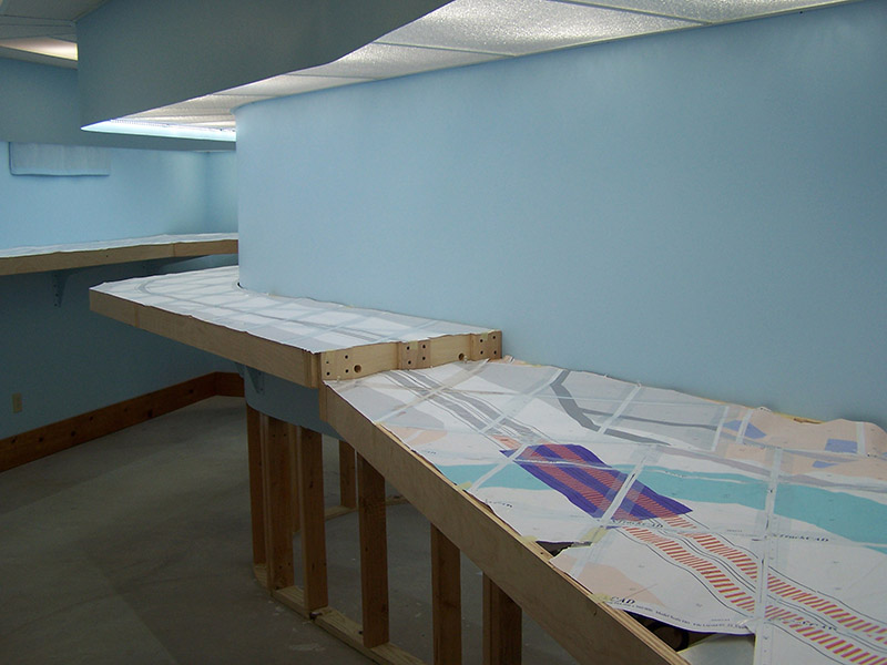
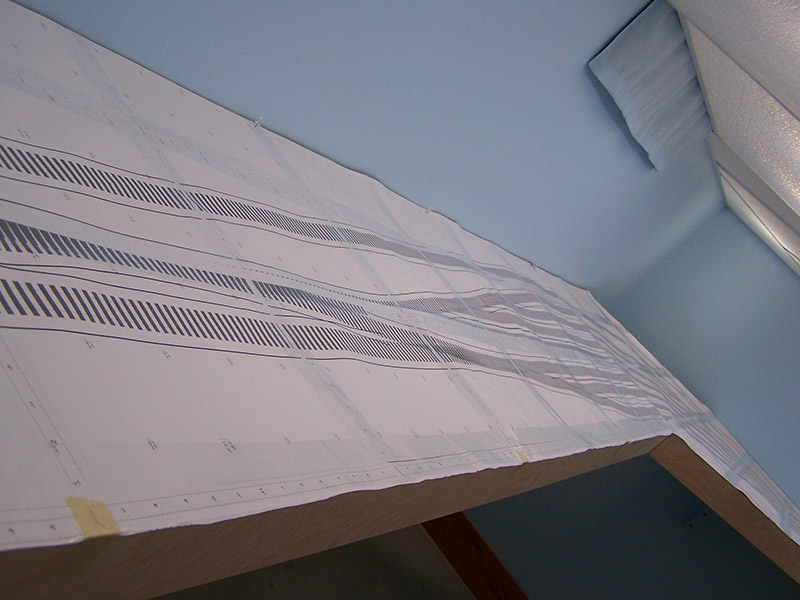
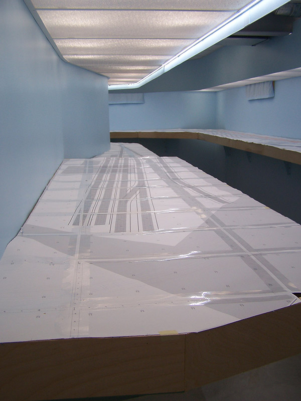
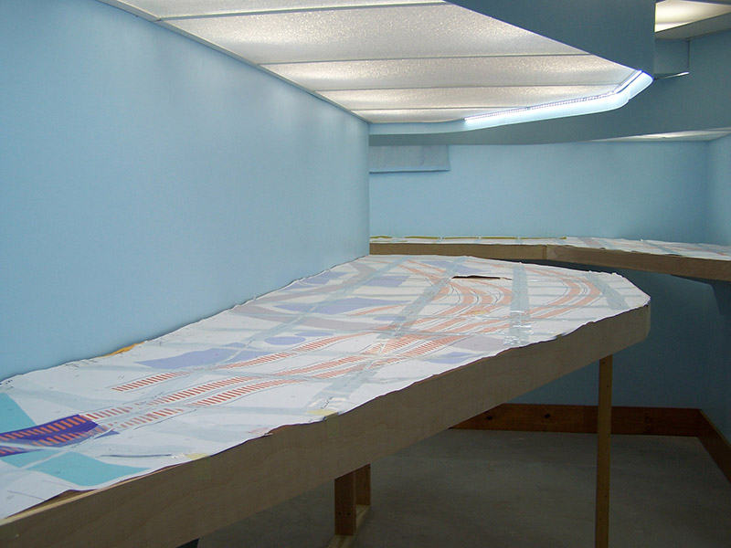
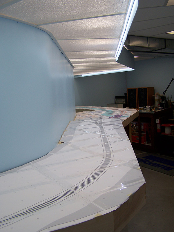
Steps 1 & 2 are complete (see previous post for the list). 1-1/2″ packing tape has been applied to the entire track plan print. This added a lot of strength and rigidity to the otherwise floppy hard-to-handle print. The three years of absorbing moisture from the air and the concrete floor didn’t do it any favors. It is impossible to get it to lay flat because some sheets have changed dimensions or curled up more than others. Also, there is a limit to how much pull I can exert on it before paper starts tearing. Ask me how I found this out. 🙂 It looks a lot wavier in the pictures than it does in person. Regardless, this appears to be as good as it is going to get.
Much of the track plan was reprinted either to repair damage to the original print or to adjust the position of tracks slightly. I printed the new portions in grayscale to save on ink, something I should have done on the original. Some damaged areas on the print didn’t matter since they won’t effect roadbed construction so I didn’t bother with those areas. Same goes for where the print meets the backdrop even though in places it is curly. Doesn’t matter.
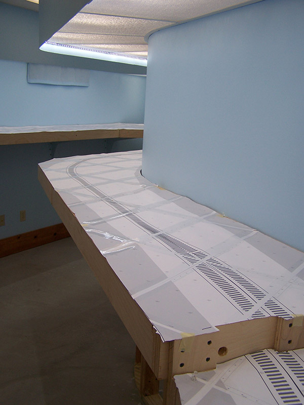
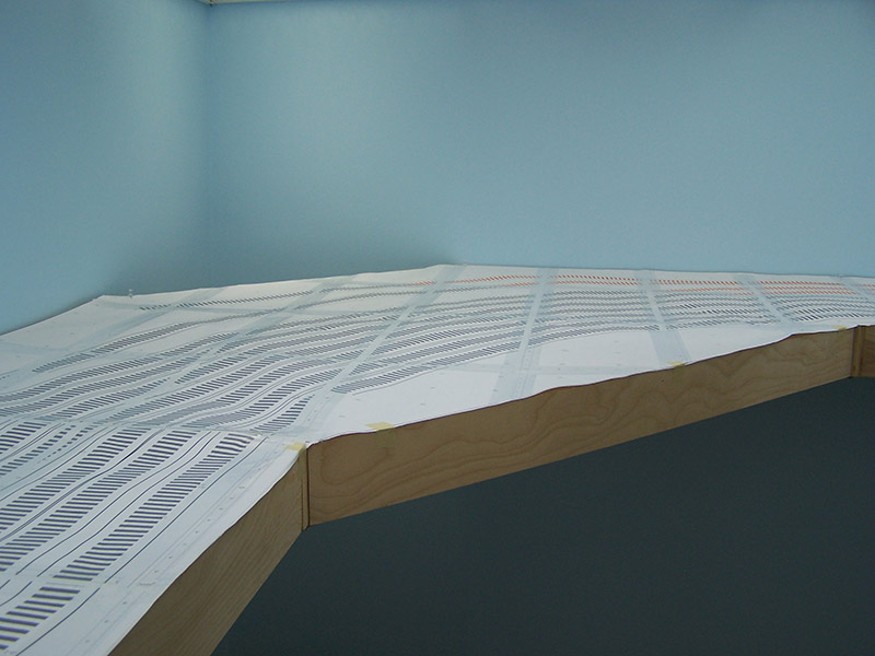
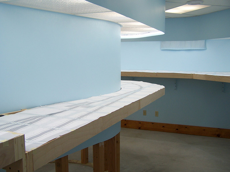
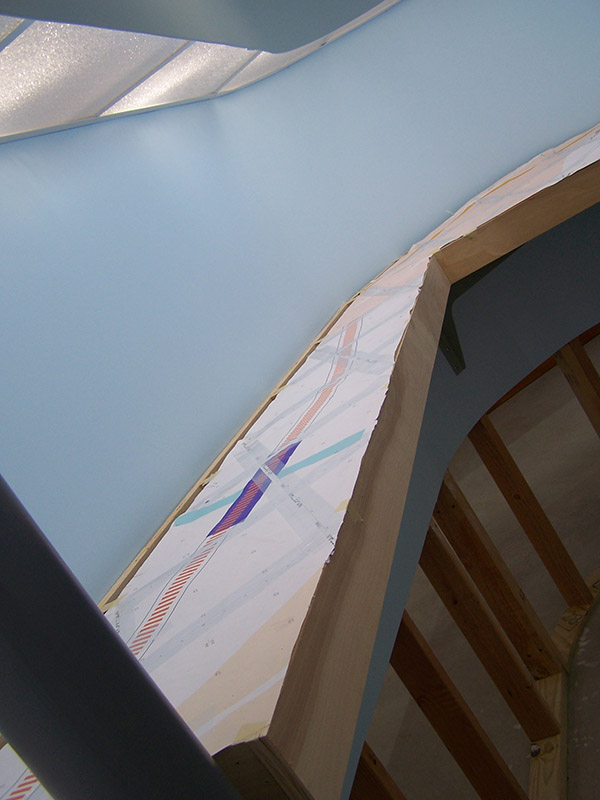
Speaking of backdrop, I elected to shift the plan slightly in this area to gain additional clearance for the trains. I have known since the beginning it was close in this spot but it

was necessary so as to not drop below 24″ radius in the curve. My minimum radius for mainline visible curves is 30″ however my minimum radius for hidden curves is 24″. The area under the left arrow is inside a tunnel hence the 24″ radius. While final positioning the plan I noticed there was a little extra space on the opposite side so I split the difference and made the clearances equal. That’s why the plan looks offset running down the shallow left hand benchwork and the plan is so crumpled along the backdrop. This change also put a very slight curve in the track just ahead of the bridge. I didn’t reprint and splice in the new curve because it is so shallow. Instead I butted the print together and re-taped. I’ll add the slight radius when I transfer the shape to plywood. I may also move the bridge an inch or so further down the line just to make sure none of the curve is on or close to the bridge end.
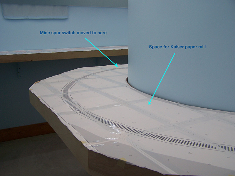
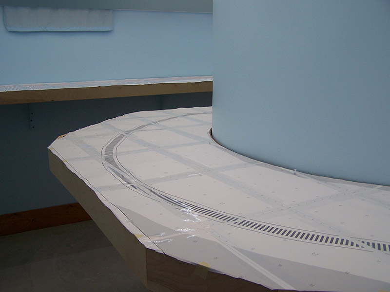
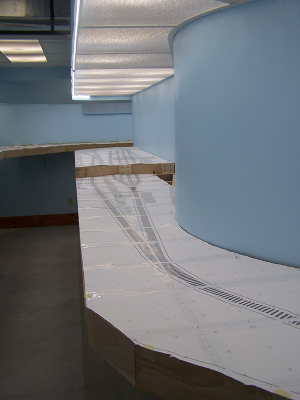
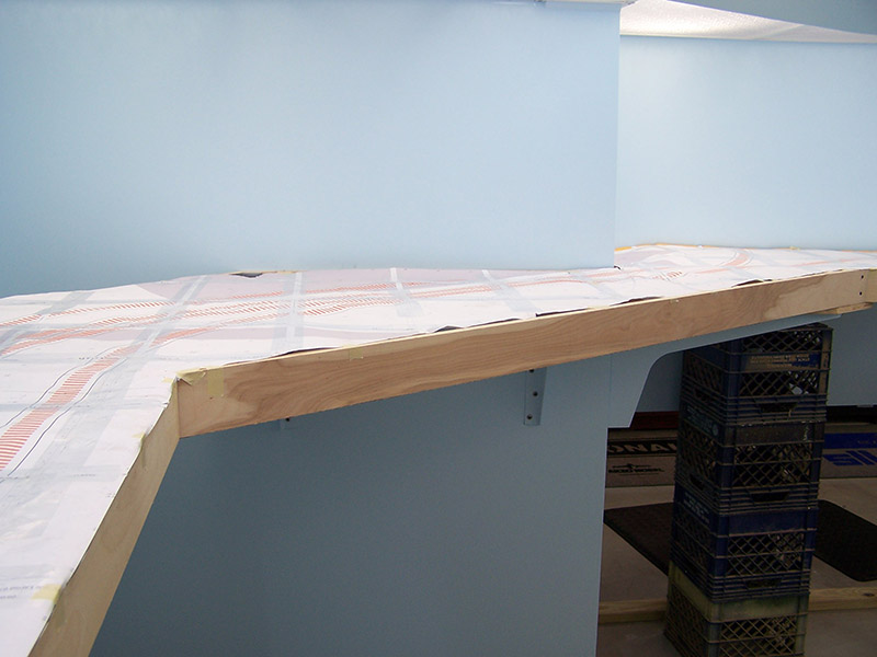
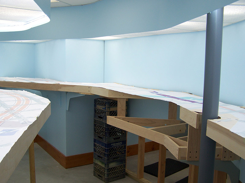
The other area where a revision was made is in the big curve around the outside of the peninsula. Having the mine branch leading off the end of the Kitzmiller passing siding ate up all the area around the curve.
I had considered once before putting a model of the paper mill at Luke (Westernport) MD in the big curve but never acted on it track design-wise. I decided to add the paper mill. Now the mine is merely a siding off the main and that’s OK. I moved the main slightly further towards the outside of the benchwork to make more room for the paper mill and its tracks. These revisions necessitated a complete reprint of the track plan in this area. Once the new plan was printed and taped I used the original plan to locate the cut for the peninsula backdrop. It worked out well.
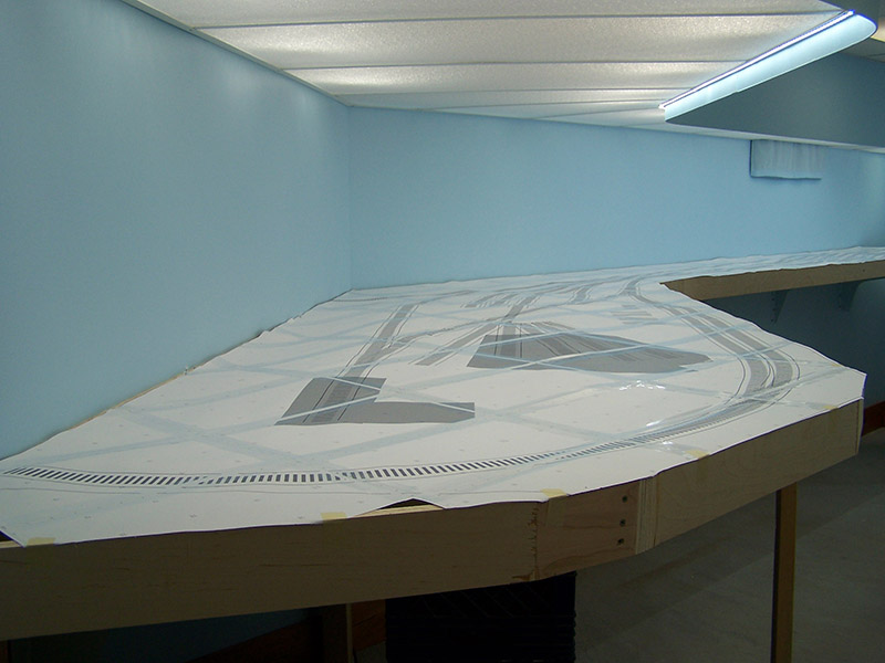
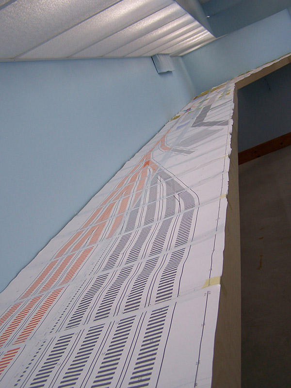
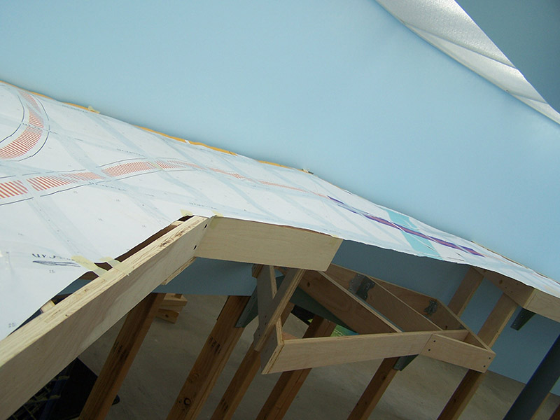
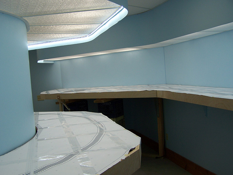
While the picture gallery in this post may look terribly similar to the prior post’s gallery, they are not the same. Take a good look at the paper track plan. This is the last time you will see it in its entirety. Next step, cutout the track and transfer the shape to plywood. There are 3 new sheets of 3/4″ birch waiting on the workbench!
Until next time,