The first three module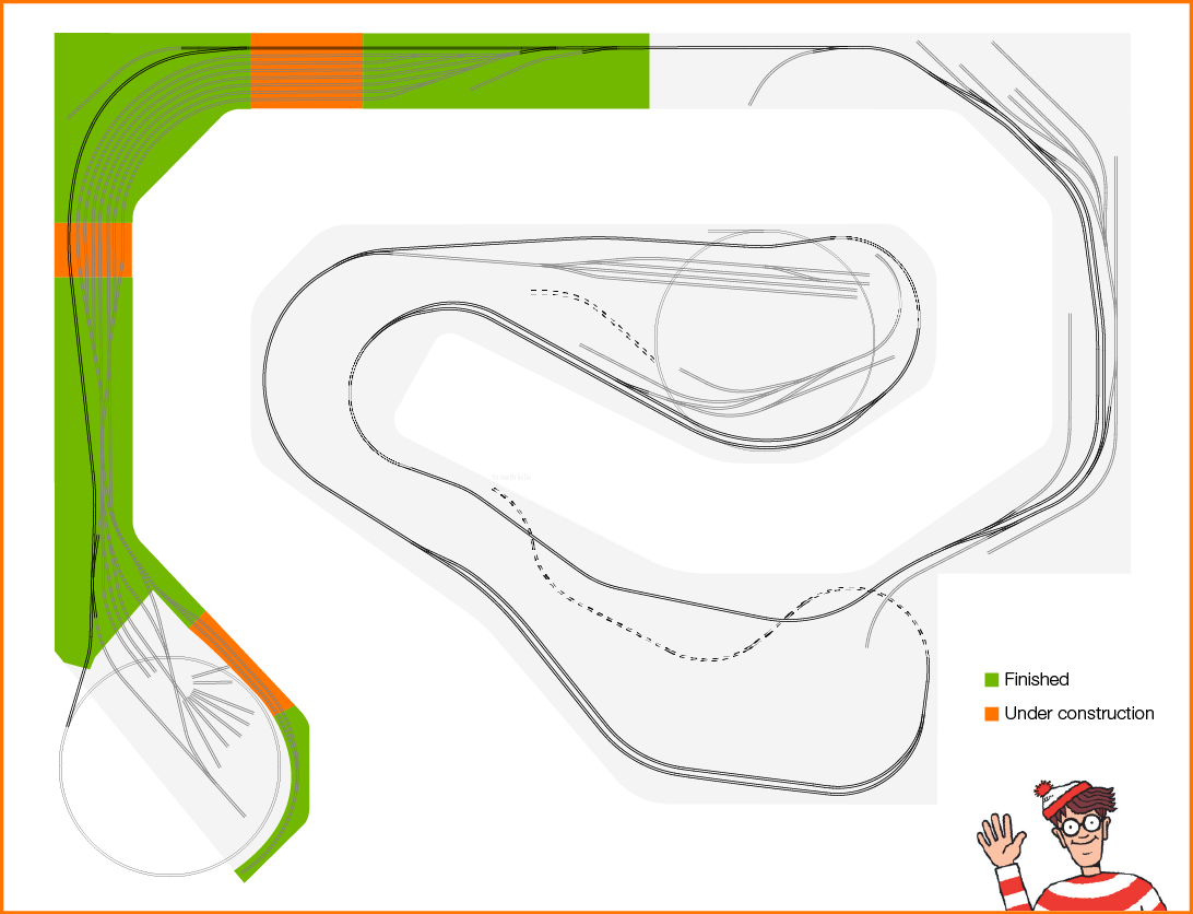 connectors have been constructed and installed. With these in place Brittain Yard is complete. Woohoo! For the first time I can run a train the complete length of the yard. It is very cool. This is also the first time I have the opportunity to walk along with a train. Prior to today it was just test running back and forth on one module.
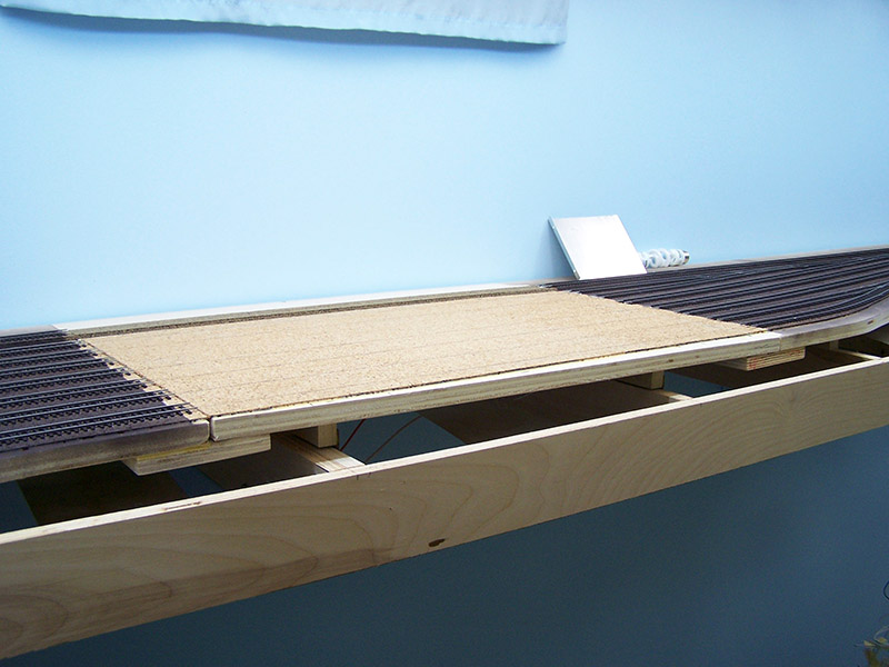
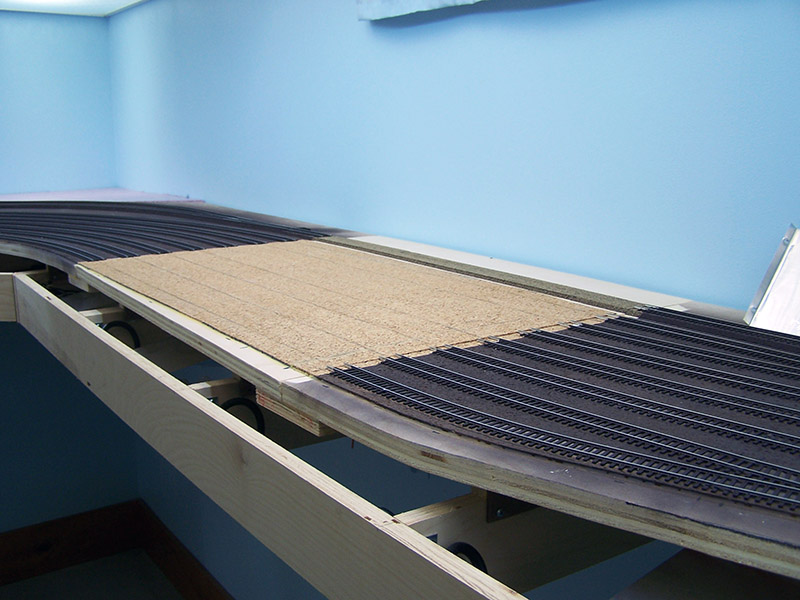
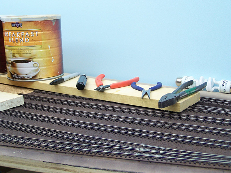
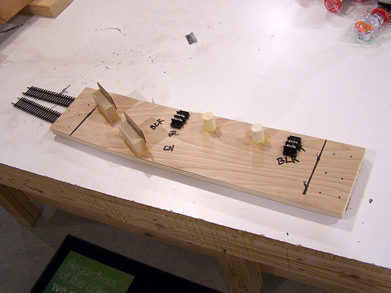
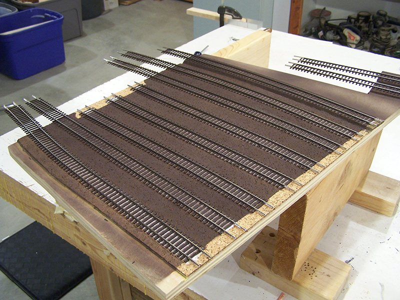
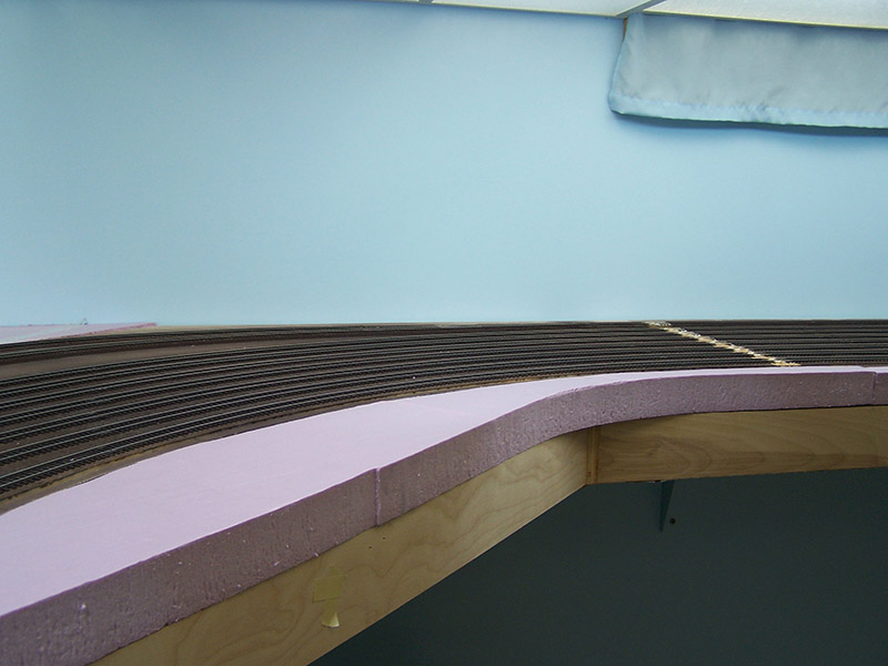
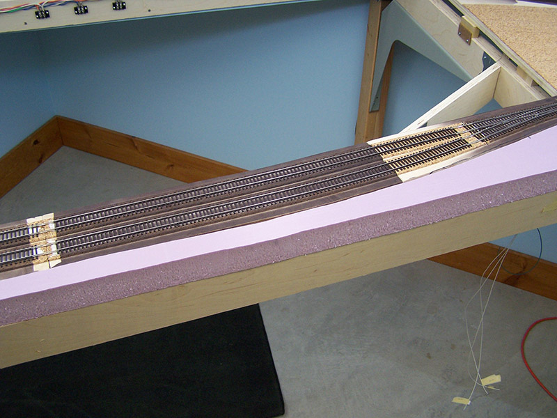
Connector #1
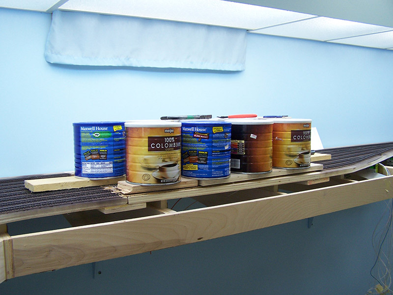
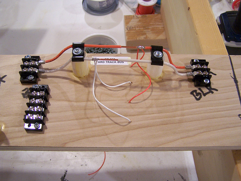
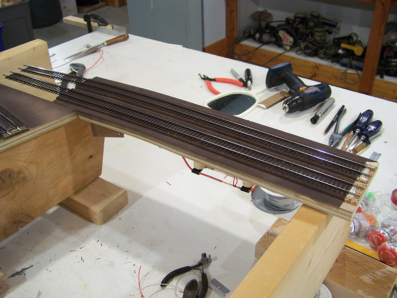
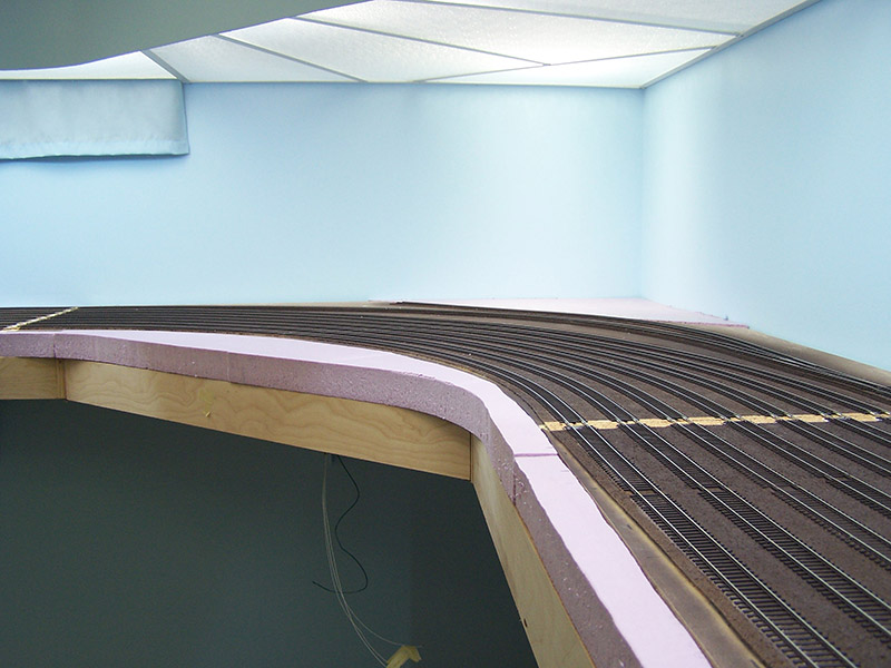
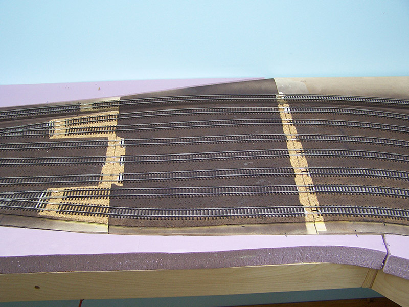
Connector #2
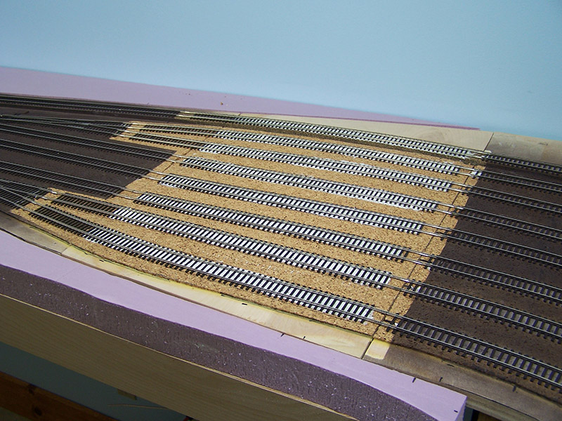
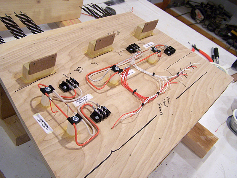
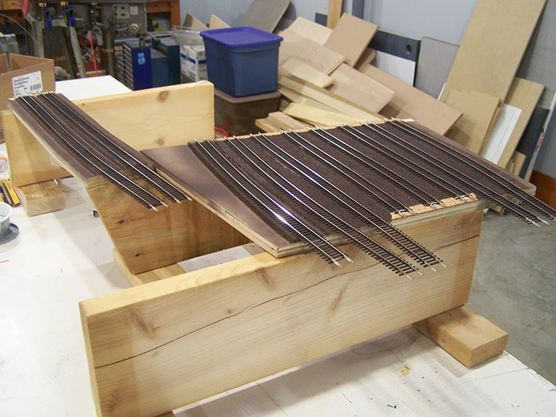
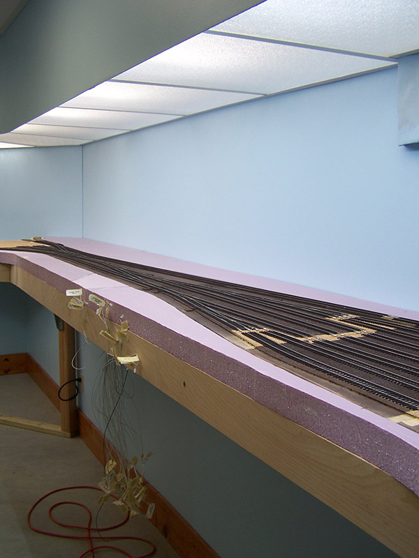
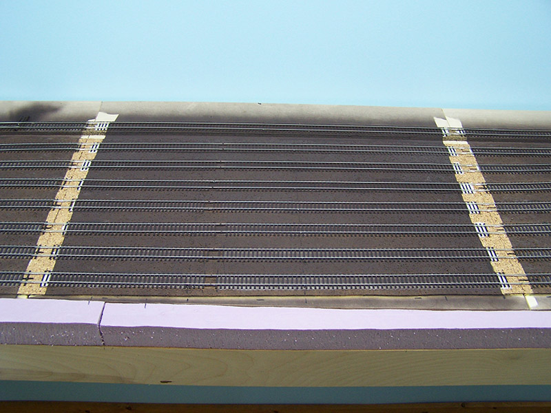
Connector #3
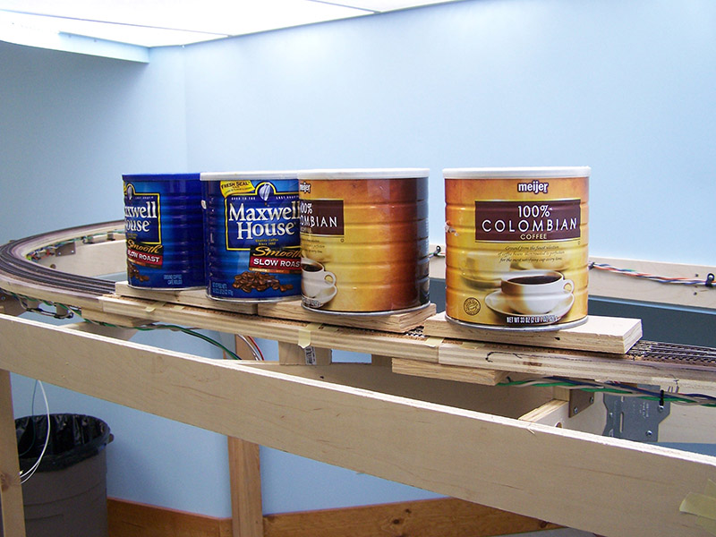
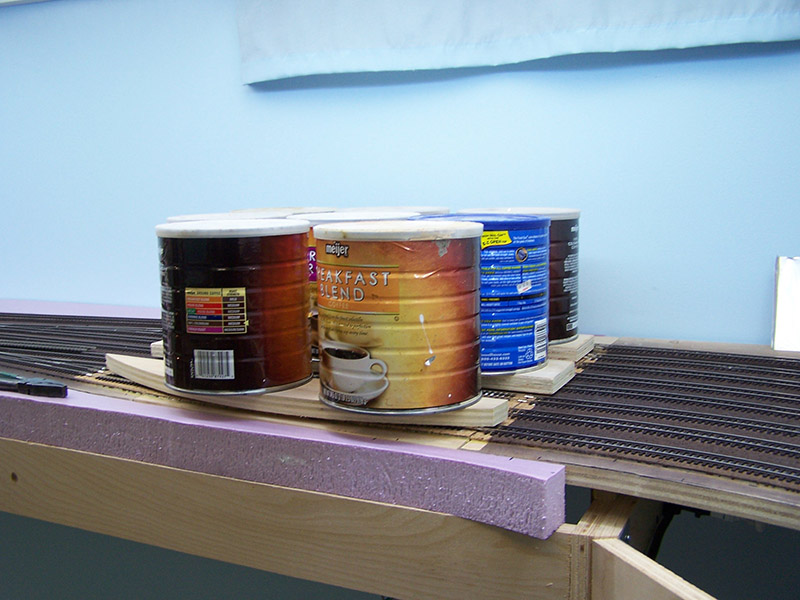
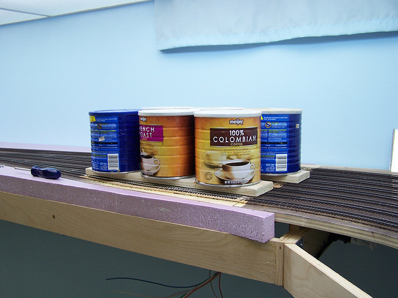
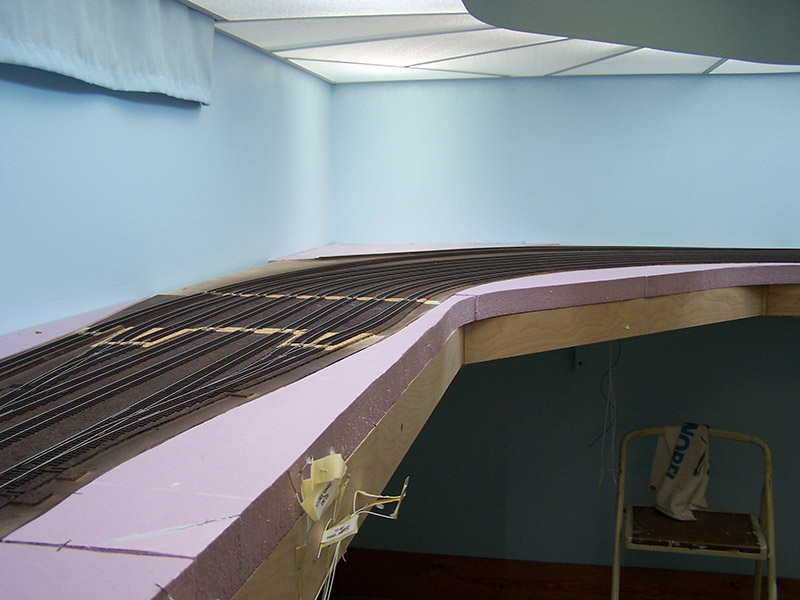
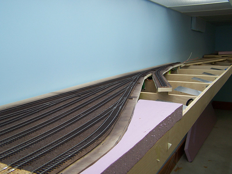
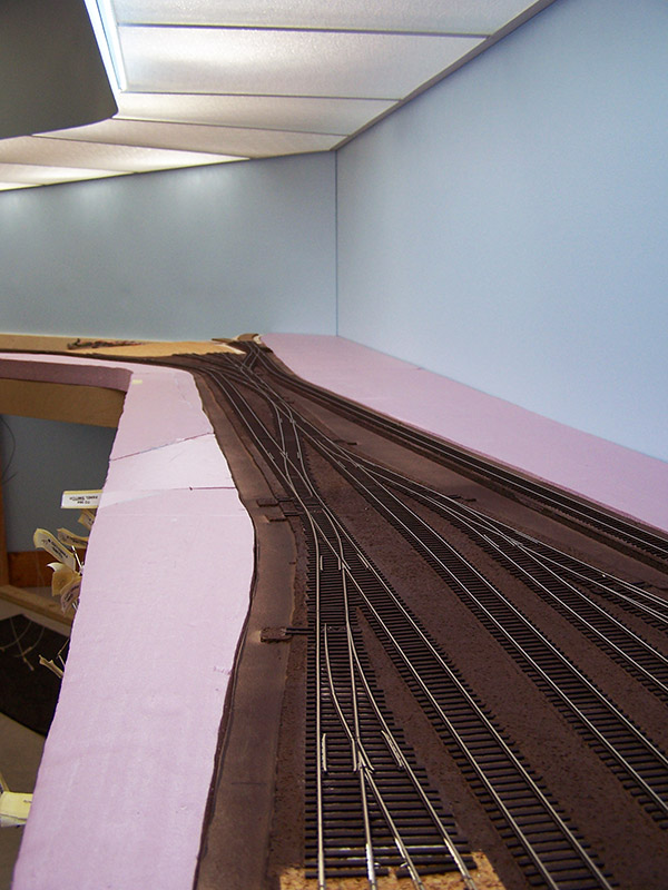
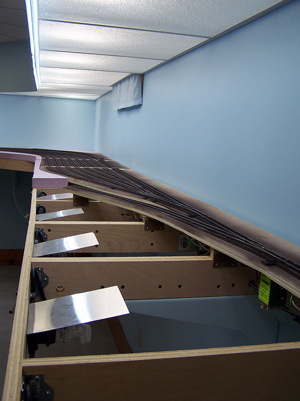
View of the yard looking east from end of Spur 4
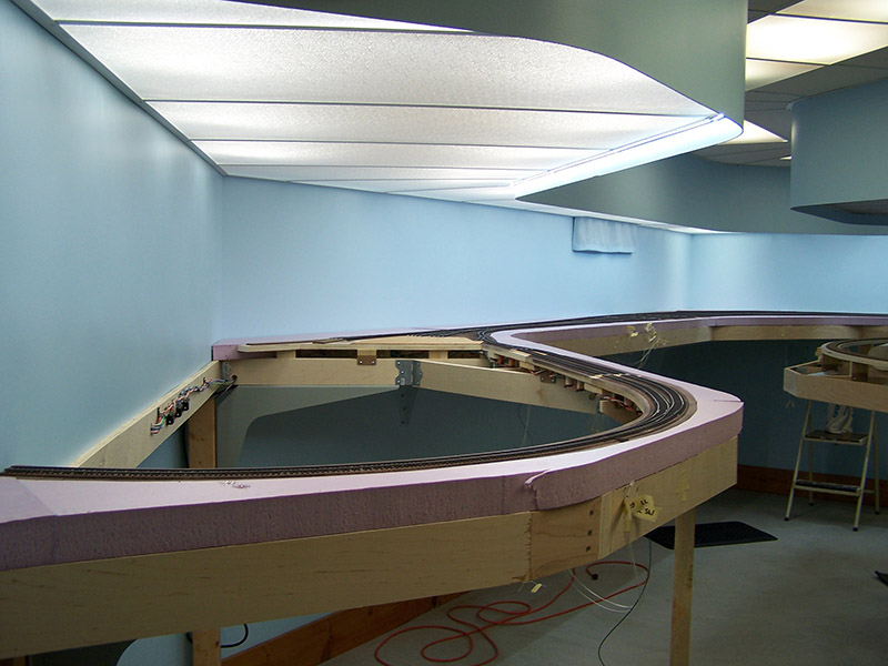
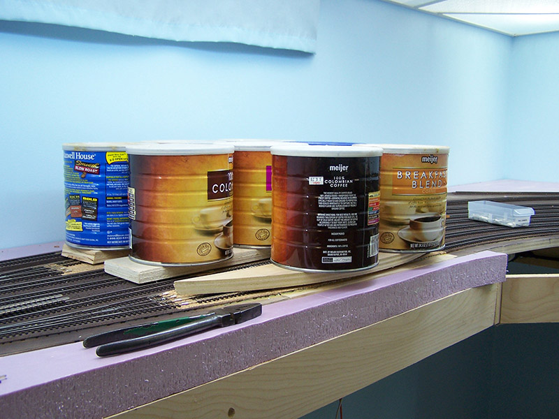
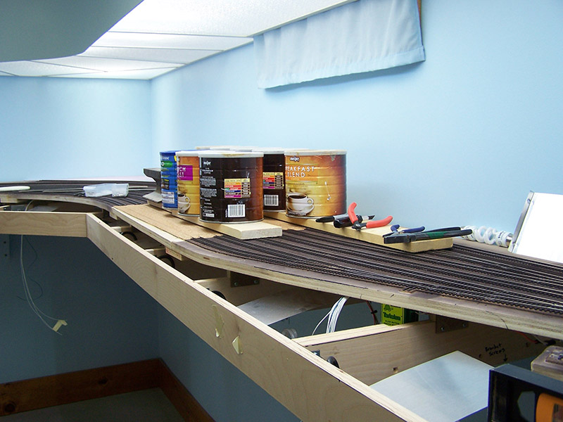
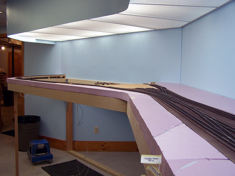
View of the yard looking west
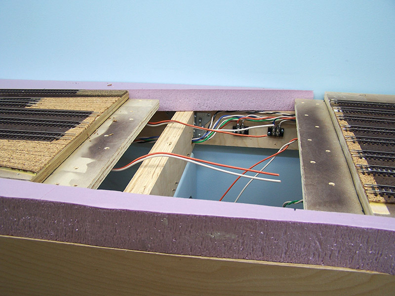
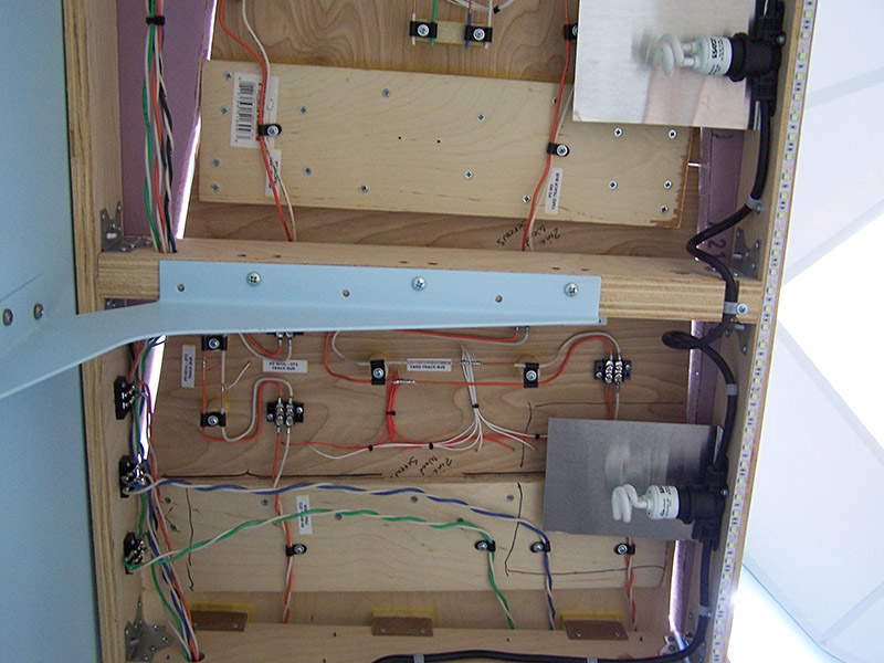
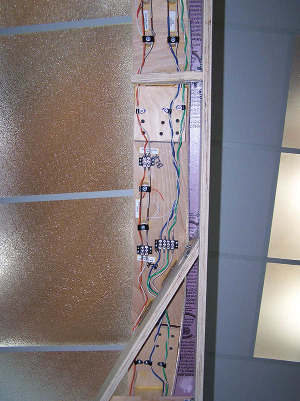
As you can see they are wired for easy removal if needed. Typically the control and accessory buses do not cross a connector. The exception so far is this connector on spur 4. The helix will sit in the center and I don’t want buses to crisscross the helix so bridging the connector with the control and accessory buses was necessary in this spot.
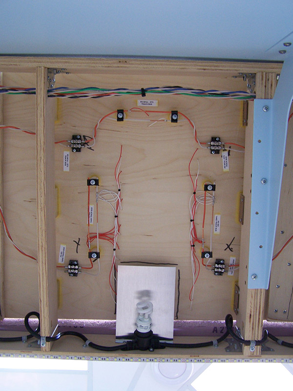
This is a more typical connector underside – track buses only. The yard is divided into two power districts (east and west). The division occurs on this connector. So, there are three buses – yard east, yard west, main.
I must admit I have spent a fair bit of time running a train around in the yard. It’s a blast! And very satisfying in that the yard trackwork performs well. Operating the switches with no control panels is a drag. I have to search through the wire tags to find the right wire to energize to throw a switch. Oh well, all in due time.
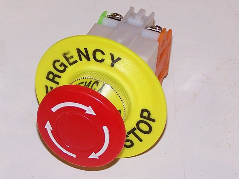
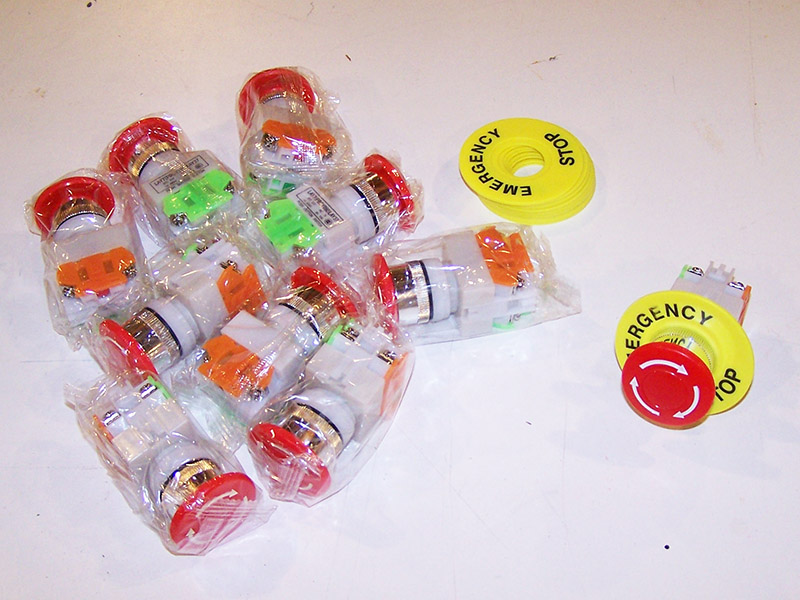
As a little side note… I received from the MadeInChina company my emergency stop switches. These will be on the control panels. If ever something goes whacky on the railroad simply push the big red button and the entire railroad will shut down. More on these when the time comes.
With Brittain Yard complete, I move further down the line. Next module – rubber factories switching area. Enjoying every minute!