Merry Christmas and Happy New Year! Between the holiday festivities I completed some of the wiring on the Brittain Yard throat module.
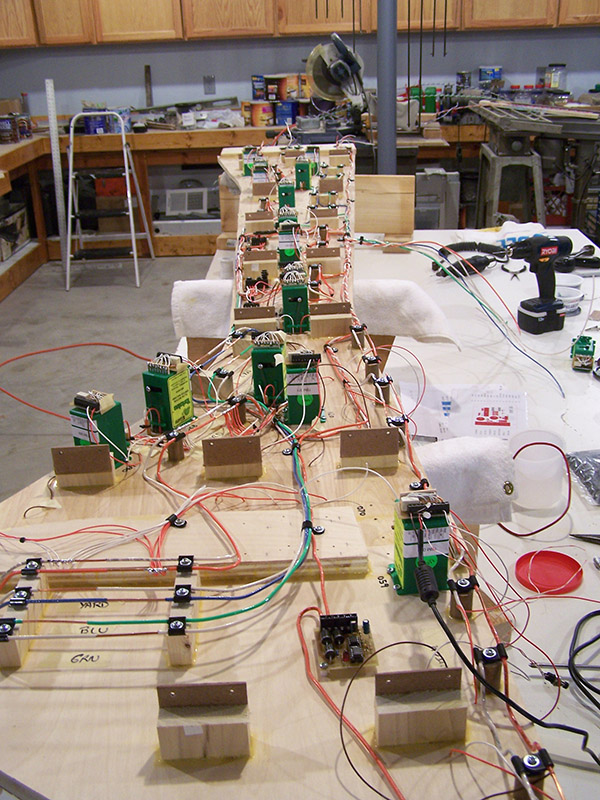
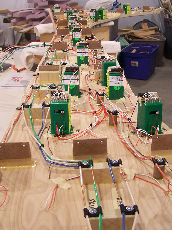
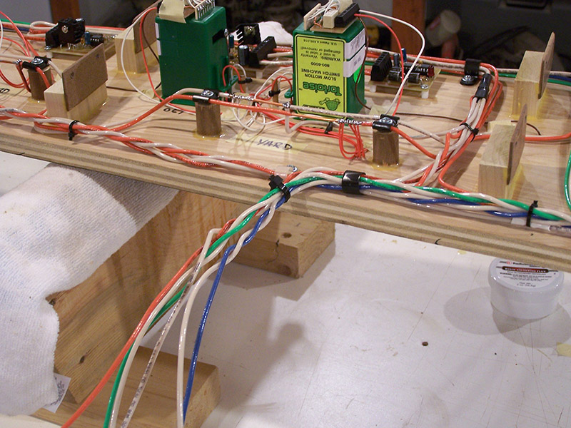
So far I have the three buses installed. The track bus interconnects and feeders are also finished. Notice the abundance of orange wires. 🙂 Control (blue) and accessory (green) wiring comes next followed by the fascia panel wiring. Wires, wires, wires!
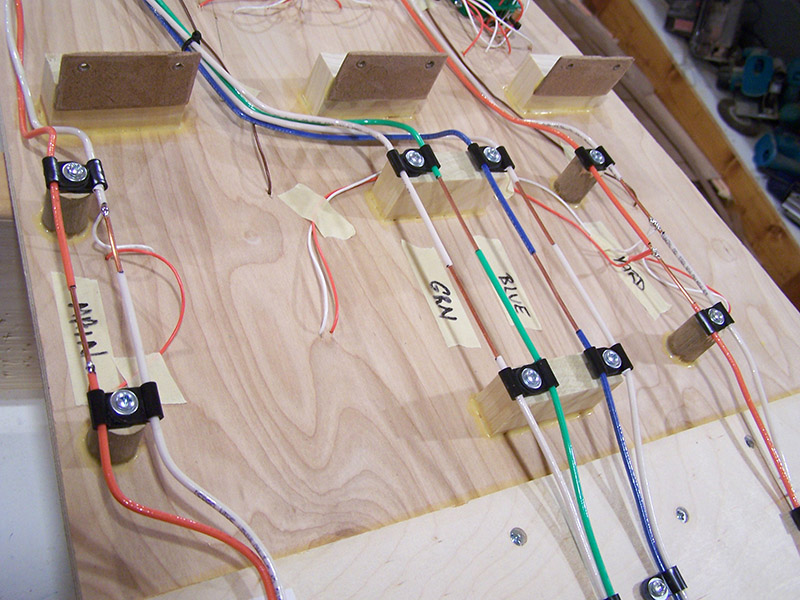
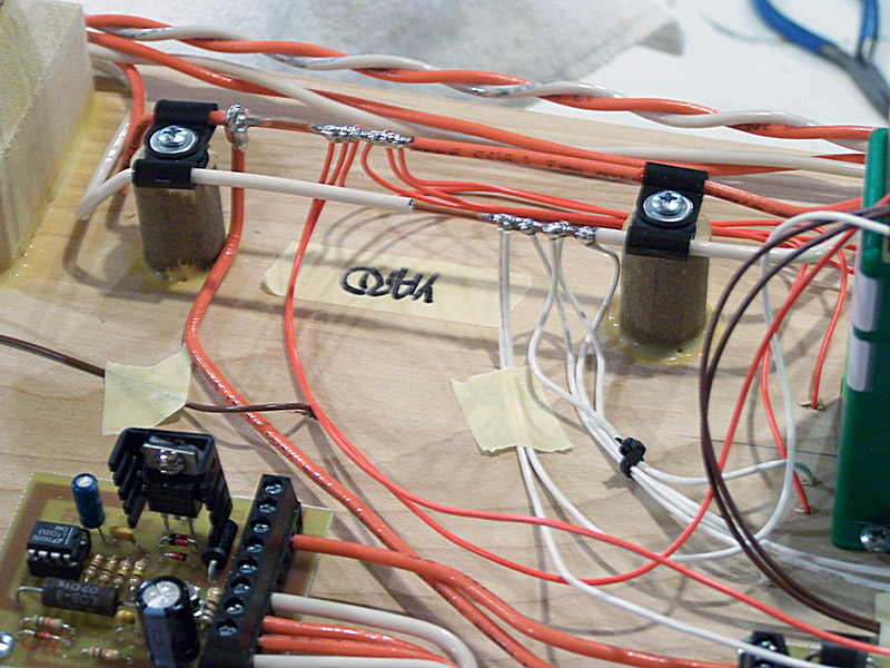
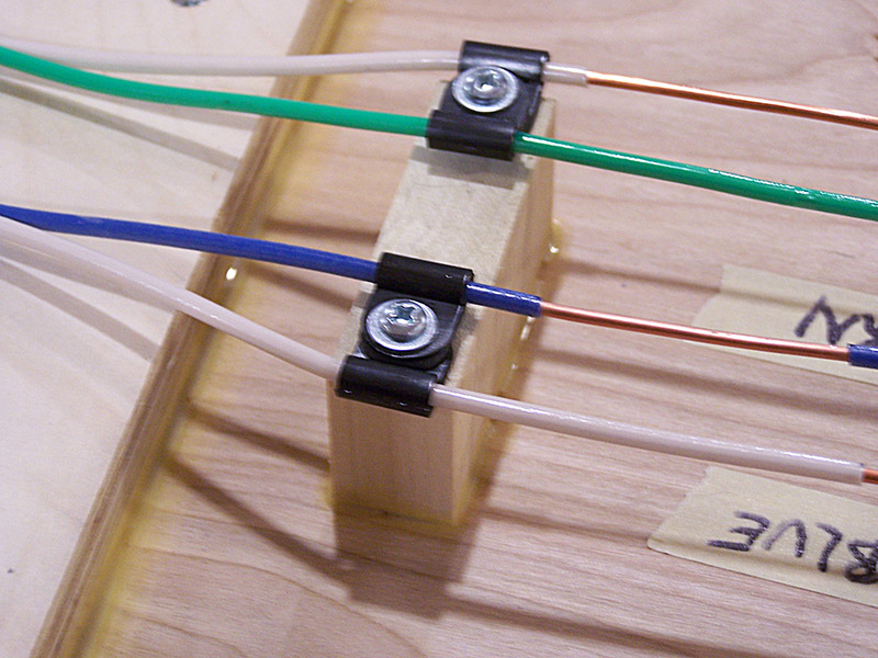
The telephone pole idea worked swell. A pair of .125″ nylon clamps on a common screw hold the 12 ga wire beautifully. They also maintain a nice spacing between the conductors. Just to be on the safe side I offset the bare copper section of each bus wire.
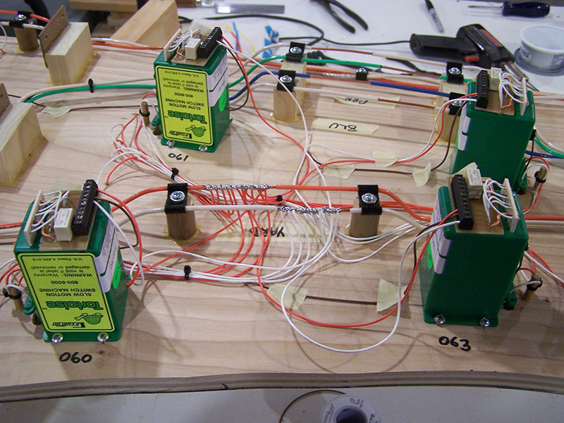
A few of the bus terminals hold quite a lot of feeders.
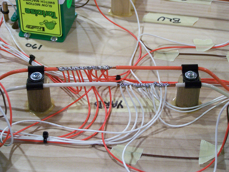
The wiring looks a bit messy right now. Only a few wire ties and clamps have been installed. I want to get the rest of the wiring installed before I make any serious attempt to secure the wires in an orderly manner. For now, masking tape is doing the job.
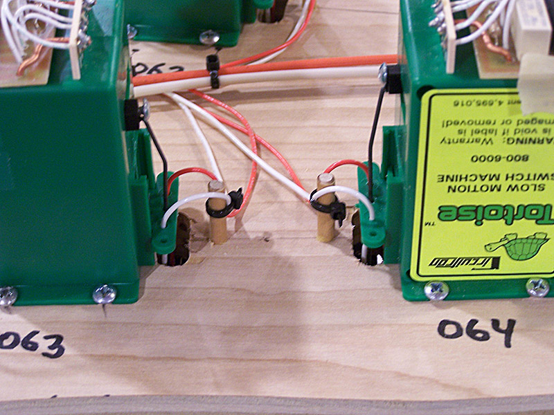
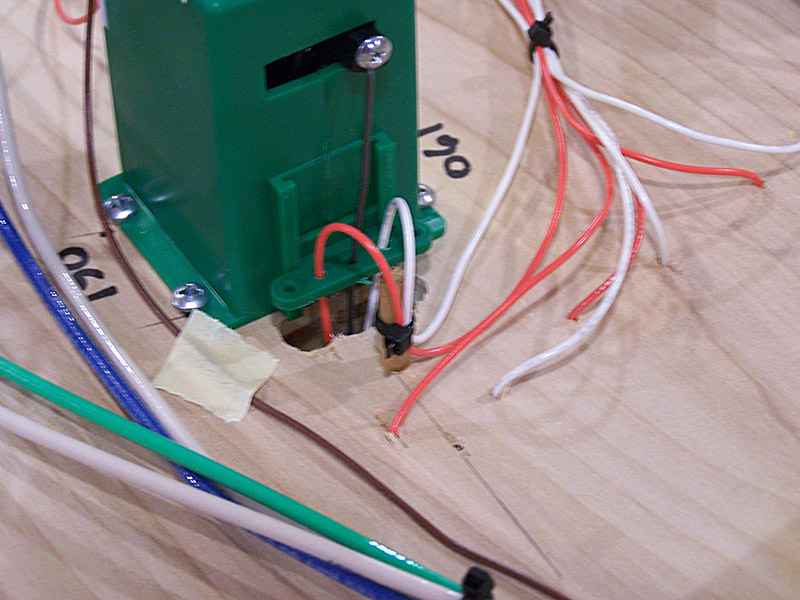
Came up with a decent solution for securing the point rail feeder wires where they exit the throw rod slot. I drilled a pilot hole and glued into it a 3/16″ x 1″ wood dowel. In conjunction with a wire tie the wires are held safely away from the moving parts and are at a nice bend that will help the wire flex as the points move.
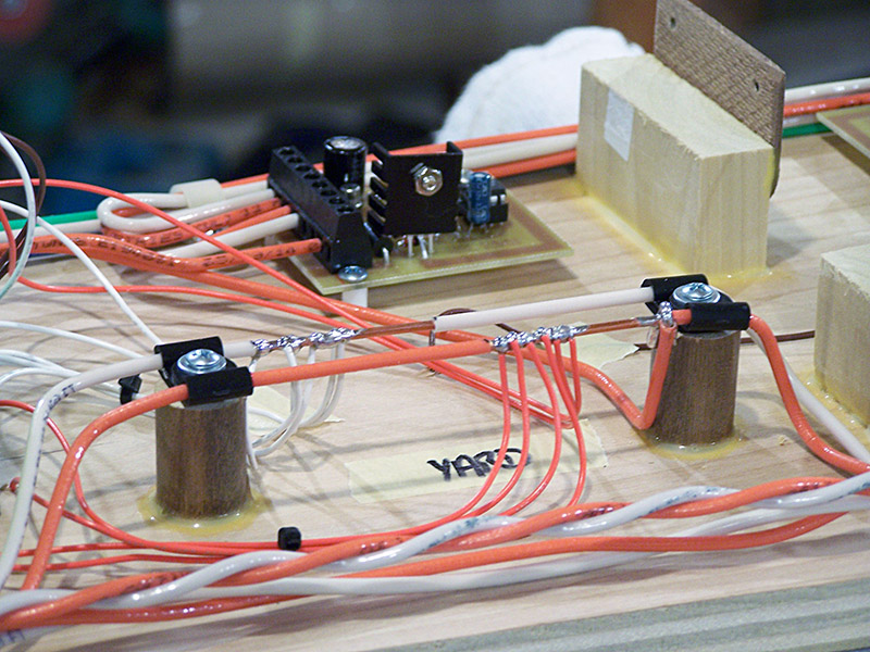
The first two of my homemade circuit breakers and occupancy detectors are installed although their wiring hasn’t been finished yet.
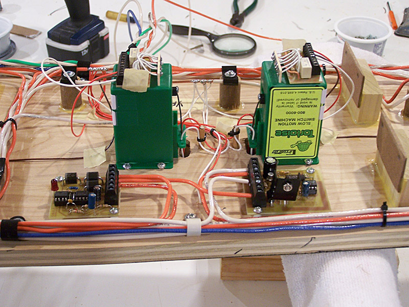
Amazingly enough all this wire terminates at a single point into only 3 pairs. These will connect with the power bus terminal strips on the benchwork.
Here, the bus lines are ready for attachment to the next module. This is necessary because the circuit breaker on the yard throat module feeds tracks on the next module.

The iron is hot and I have many more solder joints to make. See ya next post.