Following along with my blog I realize it may be difficult for readers to visualize where I am currently working in relation to the entire layout. As I am about to begin constructing the individual modules, adding a legend to the top of the posts should solve the problem.
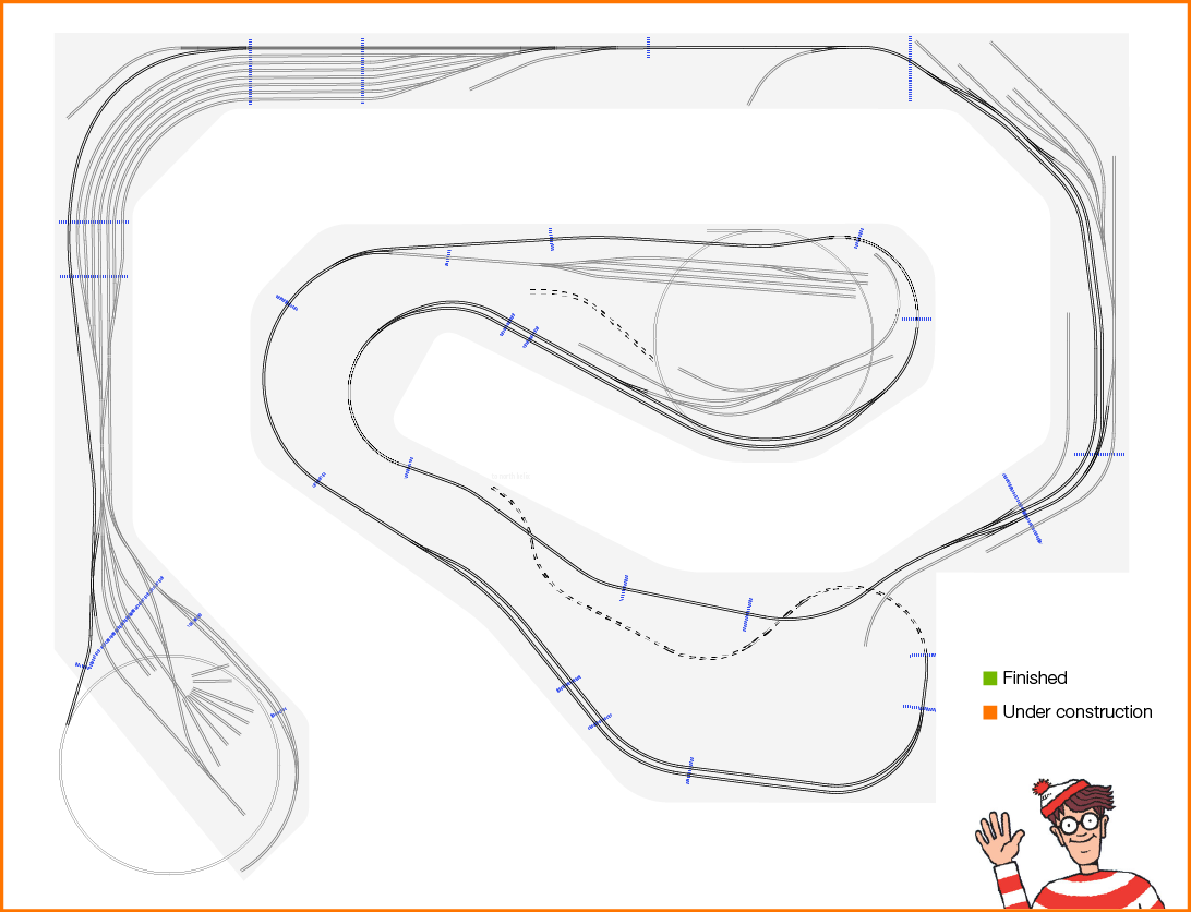
Below is the basic plan. Orange shaded will be the module(s) under construction and the subject of any one post. Green shaded will represent modules that are complete (track, wiring, tested, installed on benchwork). The blue dotted lines show the module boundaries – cuts in the sub-roadbed.
Module 1 build will be covered in detail over several posts so you get a good idea of my module building process. Modules thereafter will be a single post per module since it essentially will be a lather, rinse, repeat process all the way round the layout.
Here we go!
