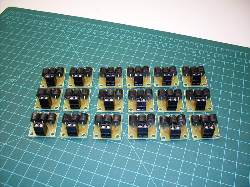
LK&O

A Railroad with Relevance

Circuit Breaker and Block Detector Final Units

Written By: Alan - Oct• 12•14

If you happen to have been following my previous post about circuit breaker and block detector design, well no further need. This post presents the final design and working units.

I have included the necessary files for download if you wish to make your own. Links are at the bottom of the post.

The circuit breaker design was good to go with the initial design. A slight adjustment of a few component values is all that was needed. The block detector was a completely different story. Even though the original author claimed the circuit can sense very small current on the track I was unable to replicate the results. The circuit required a locomotive under power for it to register block occupied. I wanted something much more sensitive. Something that would indicate occupied with only a single 15K ohm wheel set resistor on the tracks. The solution was to add a third diode in series to increase the voltage drop. You will see that addition reflected in the below pictures. The additional voltage drop was compensated by adjusting my track power supply higher. A setting of 16.9 volts yielded a track voltage of 14.8 volts after the detector.

The second issue I encountered was a very poorly shaped, slow rising and falling detect signal. I suppose I should have known this would be the case since the original circuit used only a transistor and RC network capacitor/resistor to control the detect signal. I wanted something with a clean, sharp on/off signal that I can feed directly to the signaling logic circuits (yet to be built). You notice I added a 555 timer chip as a one-shot with a full 1 second pulse width. The 555 is triggered by the optoisolator output transistor. The 555 switches from zero volts to almost 12 volts, the accessory bus power supply level. Once in the high state, the 555 stays high for 1 second then drops cleanly back to zero volts. The 1 second delay compensates for any rapid multiple triggers caused by train wheels momentarily losing electrical contact with the rails.

Both circuits have been fully tested and they work great. Confident the circuits are sound I set about mass producing them on PCB. Here is a picture of circuit breaker No. 1 and block detector No. 1 off the assembly line.

100_6462


Here are images of the final PCB design.

breaker 11 detector 11


And here are the files to build your own.
(both boards use Molex 38544 series connectors)

Circuit Breaker

PCB mask (Adobe Illustrator CS6)
PCB mask (EPS)
PCB mask (PDF)
Component list and board placement
Schematic

Block Detector

PCB mask (Adobe Illustrator CS6)
PCB mask (EPS)
PCB mask (PDF)
Component list and board placement
Schematic

Voltage Dropper

PCB mask (Adobe Illustrator CS6)
PCB mask (EPS)
PCB mask (PDF)
Component list and board placement

UPDATE

Breakers are done!

100_6467a


UPDATE

Occupancy detectors are done! All 32 of them.

100_6475a


The workbench during circuits mass production. The plastic bins started out with a lot more components in them!

100_6473a


100_6470a


UPDATE

Added PCB mask and parts list for voltage dropper board (above). These are needed for sections of track that are not on an occupancy detector. It keeps the track voltage the same between detected and undetected track.

100_6979

Share