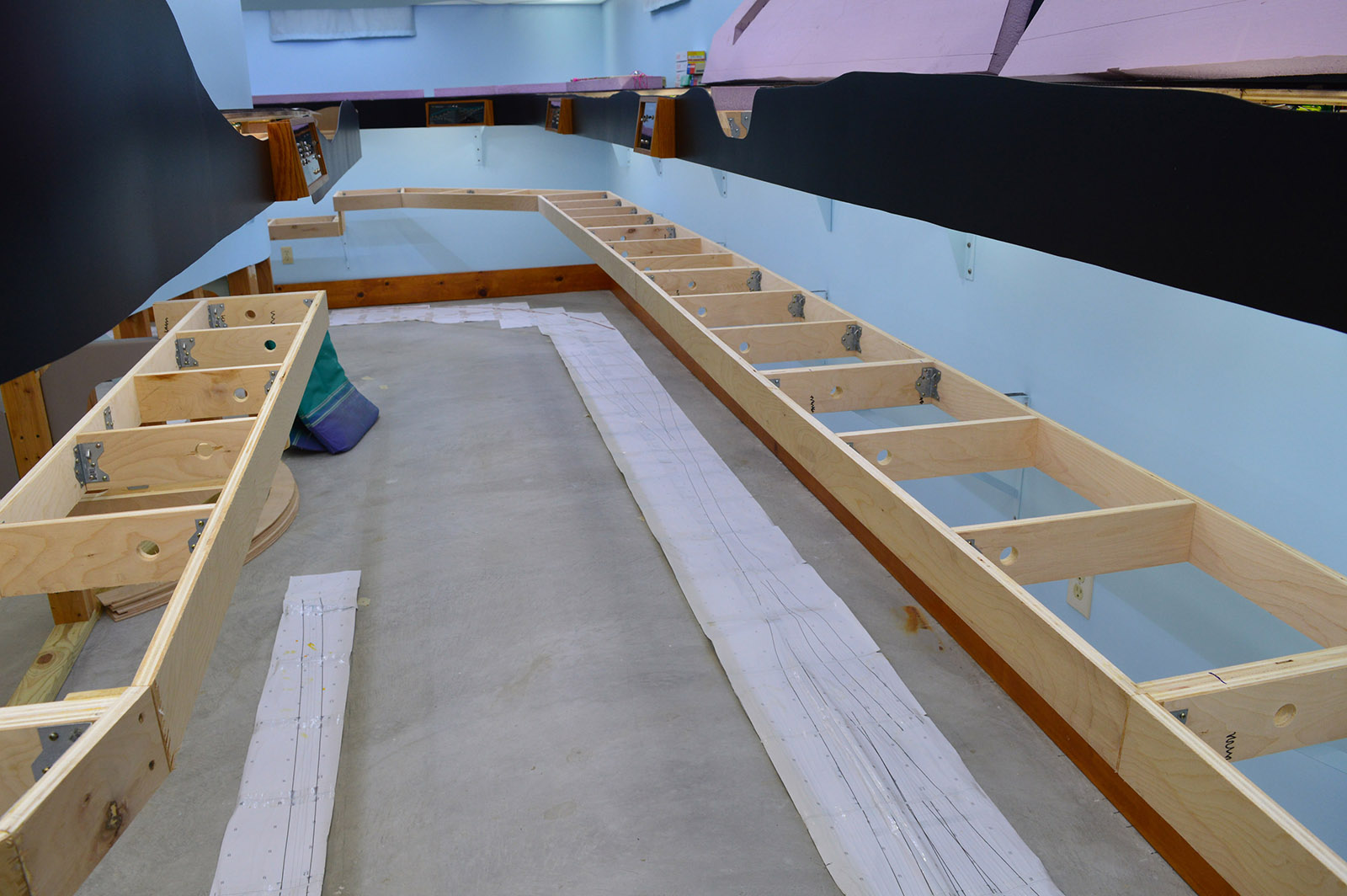
Woohoo, the lower deck benchwork is no longer laying on the floor. It’s a good thing too. We had a sump pump failure in the middle of a three day rain that resulted in us awakening to 2″ of standing water on the basement floor. Made a helluva mess and a ton of work drying out everything. Actually, the pump itself didn’t fail. The little clamp that held the float valve cord rusted away allowing the float to hit the sump lid without tipping enough to trigger the pump. Why a pump manufacturer would use a plain zinc clamp in a continuously submerged application is beyond me. I replaced it with a nylon clamp and all is well now. I also added a high water level alarm, something I should have done long ago. Live and learn.
Shelf brackets
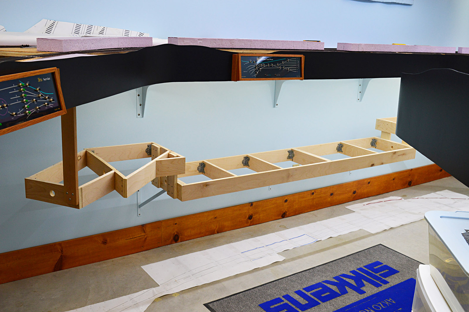
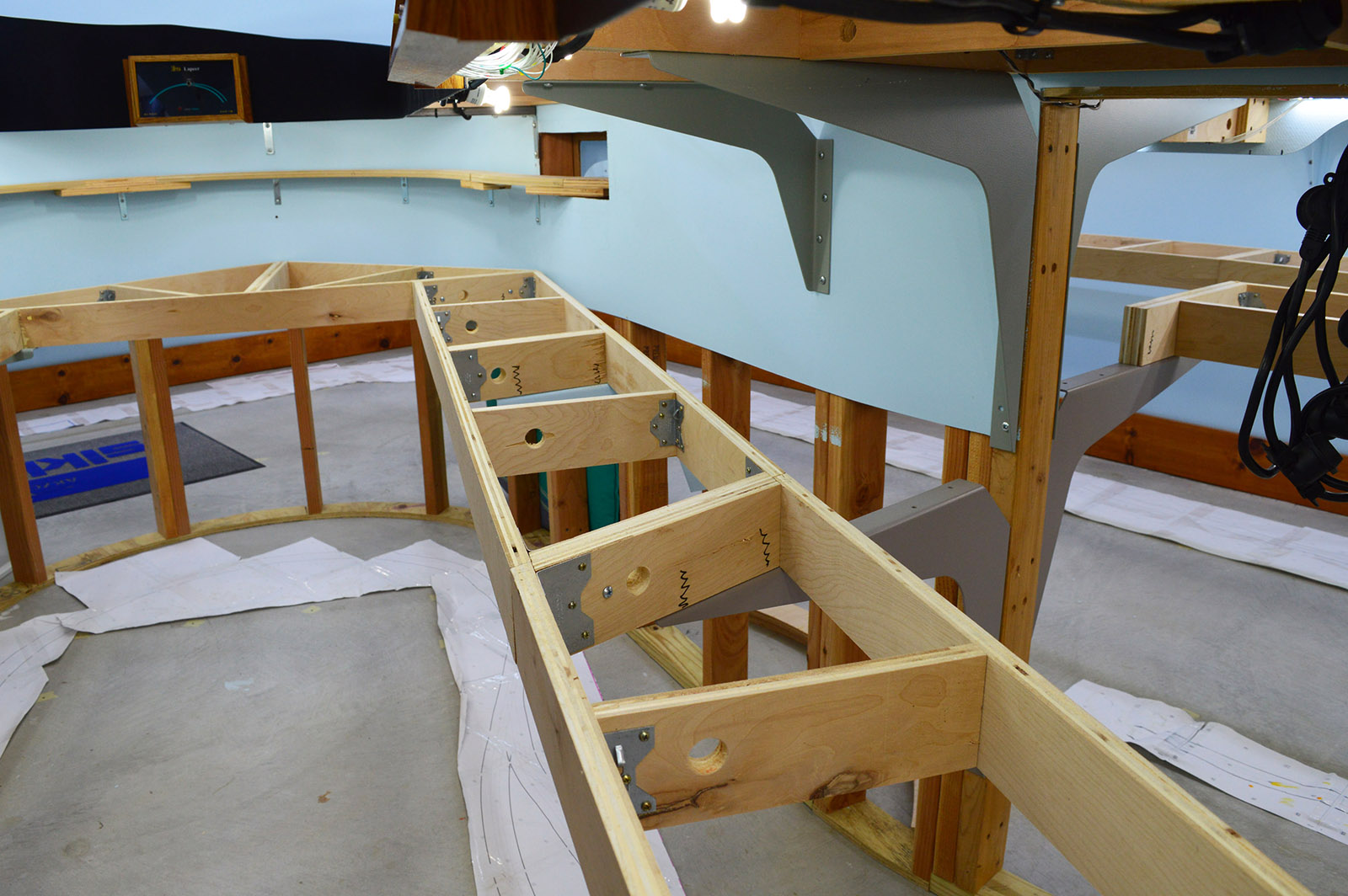
To support the upper deck I used workstation brackets made by A&M Hardware. The arched design results in less bracket intruding into the lower deck scene. The A&M brackets are super strong 1/8″ steel capable of supporting 1000 lbs per pair according to their description but they are quite spendy. A pair of 21″x15″ brackets cost $50. Since intrusion into the scene was not a concern for the lower deck supports, I let economy rule the day. Found these 22″x12″ shelf brackets on Amazon for only $4 each! They are no match for the A&M brackets in strength but more than good enough to support a train layout.
Here you can see the profile difference between the two different bracket styles:
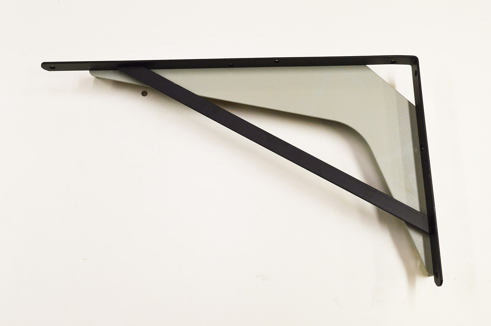
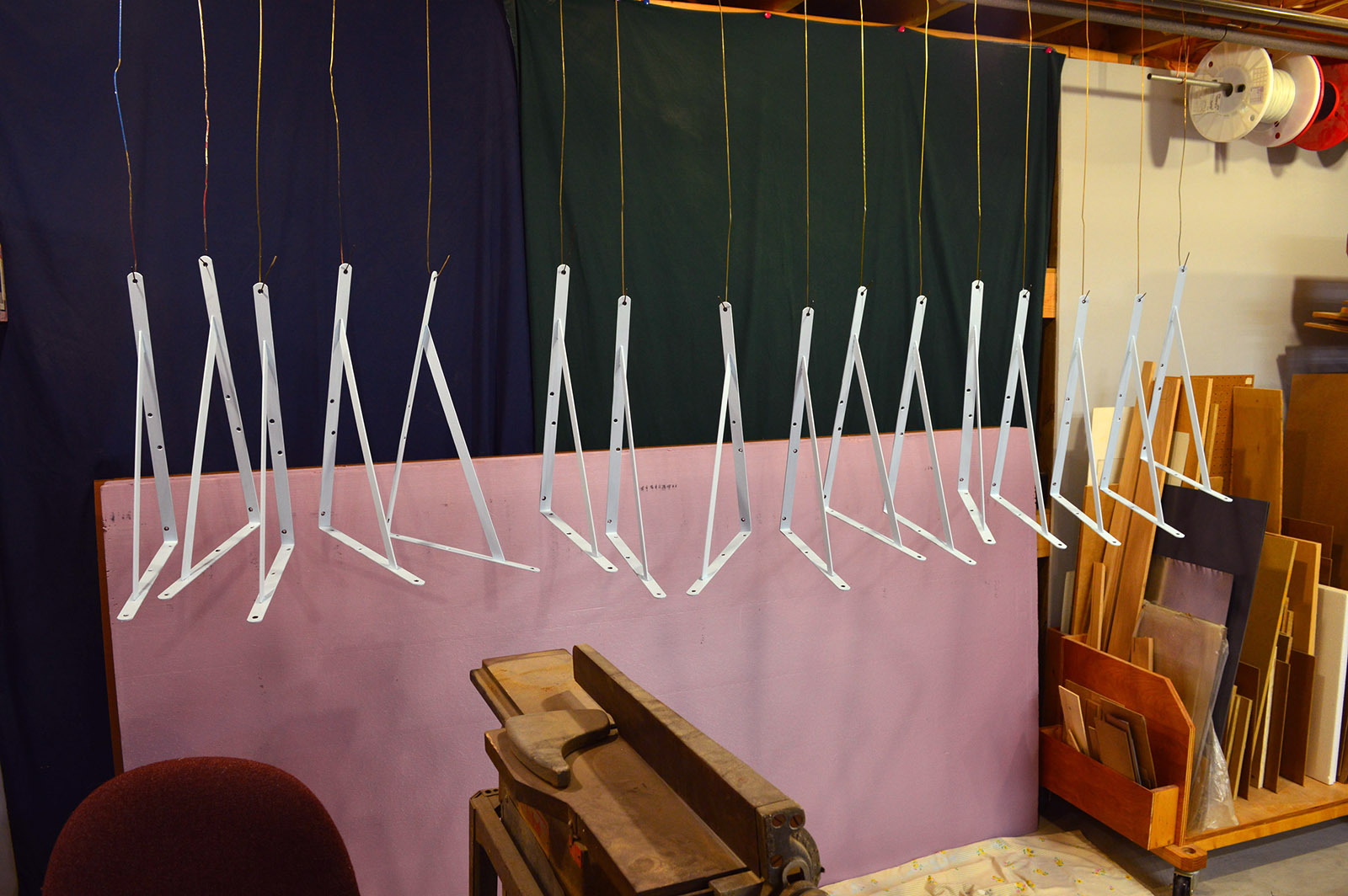
A couple coats of Serene Sky blue paint made sure the brackets would fade away on the wall.
Up, up and away
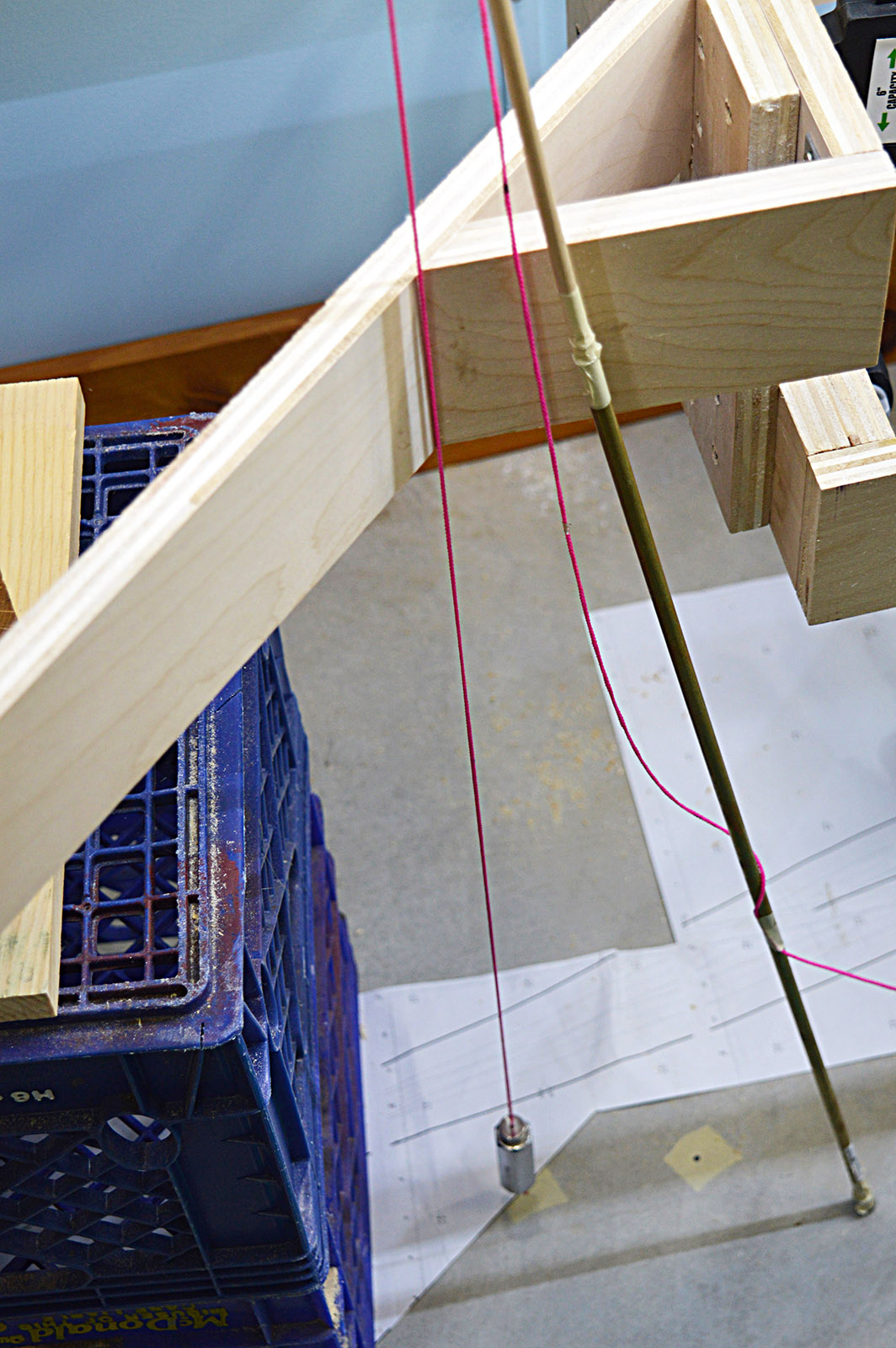
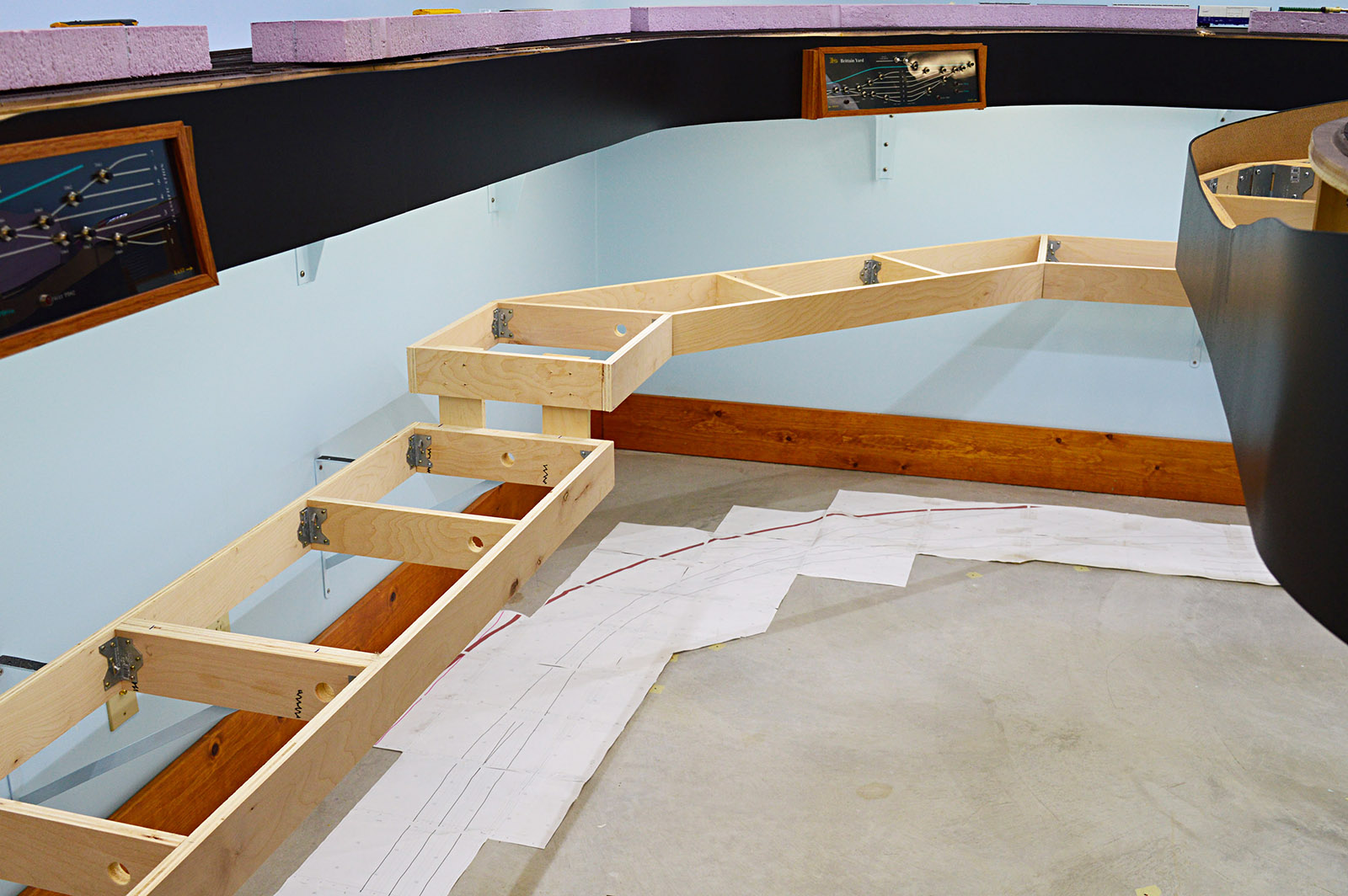
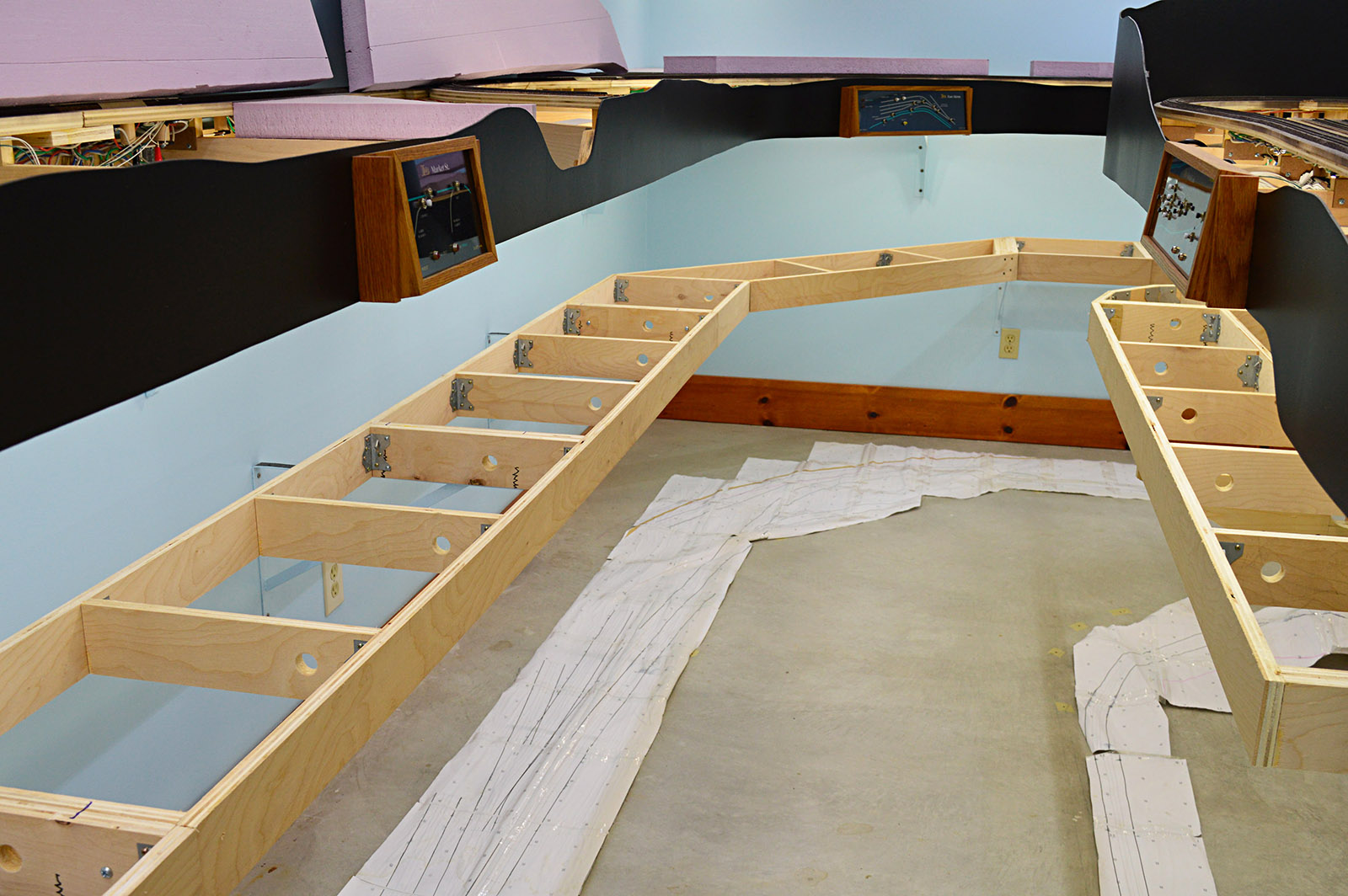
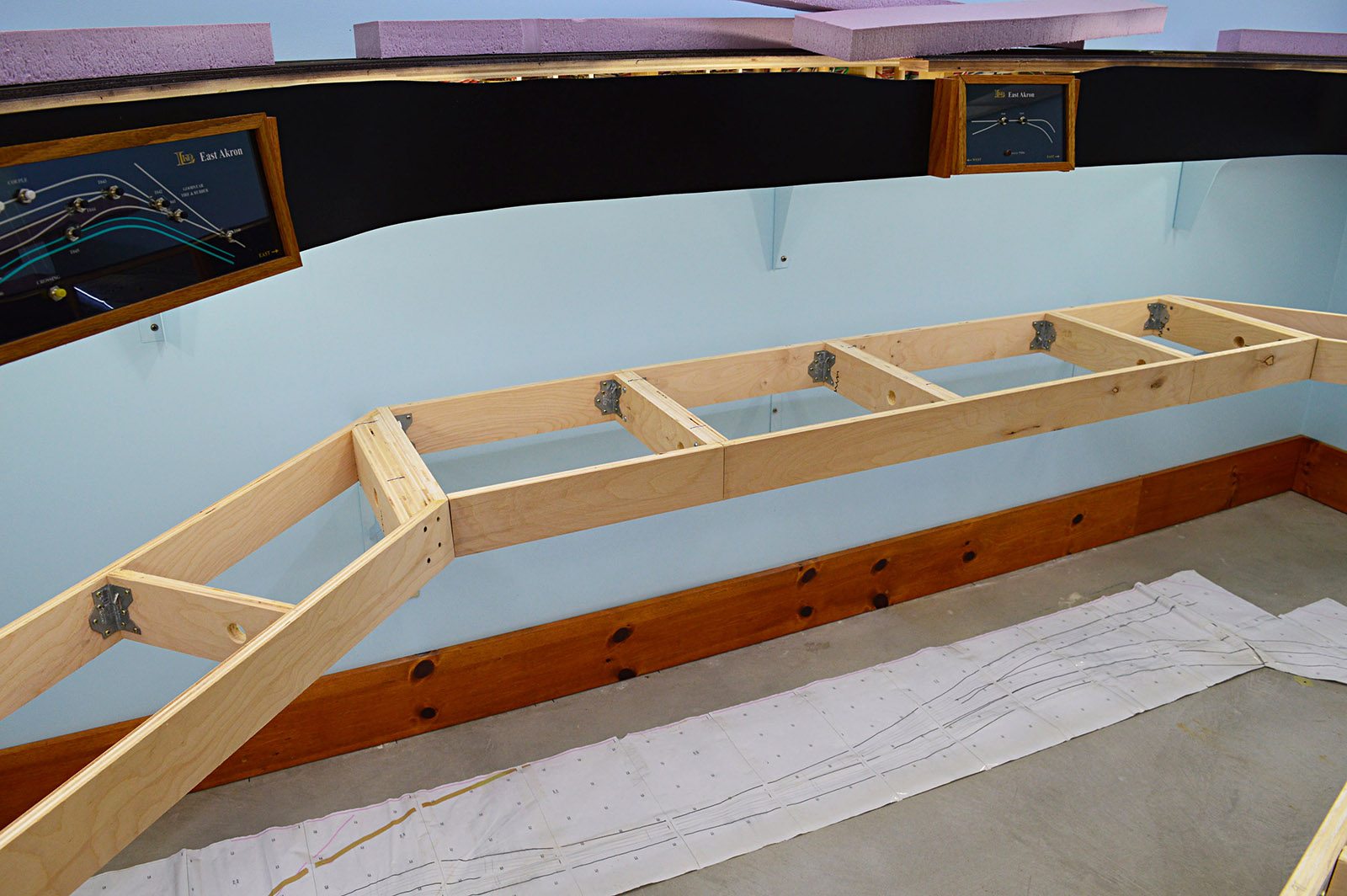
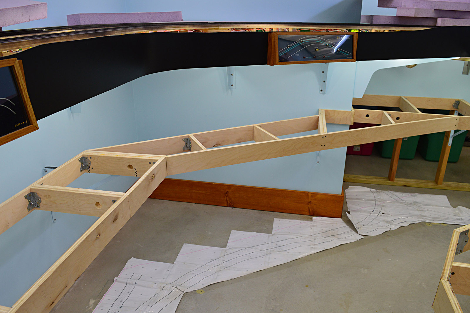
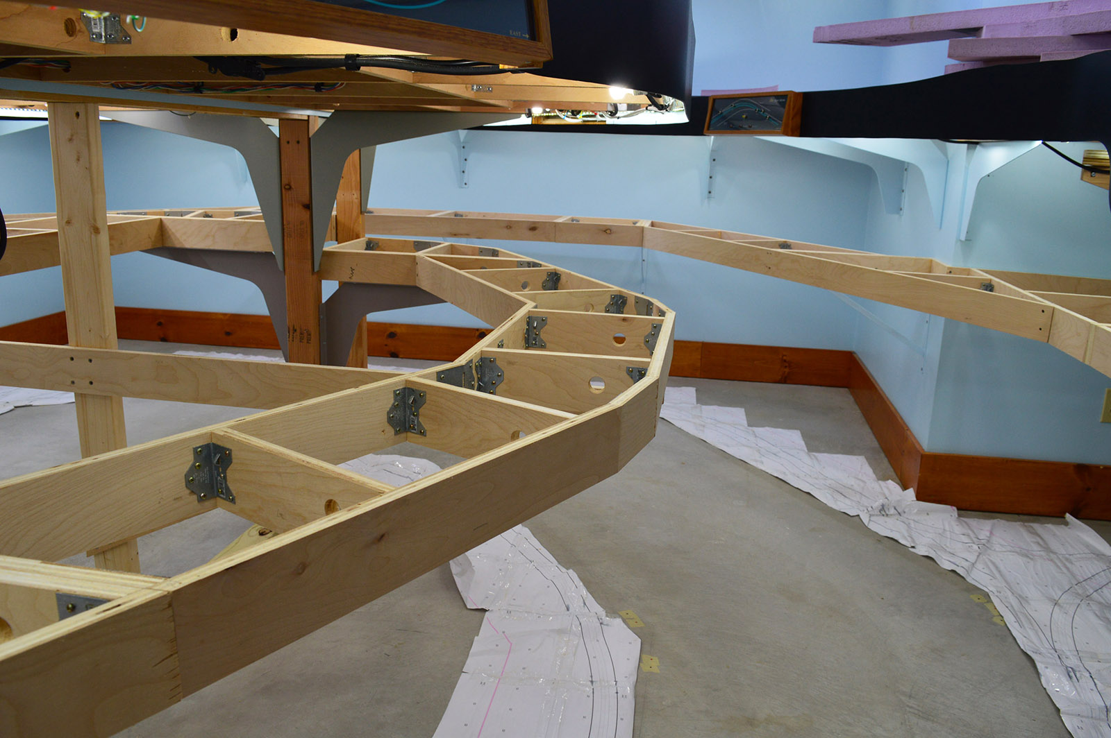
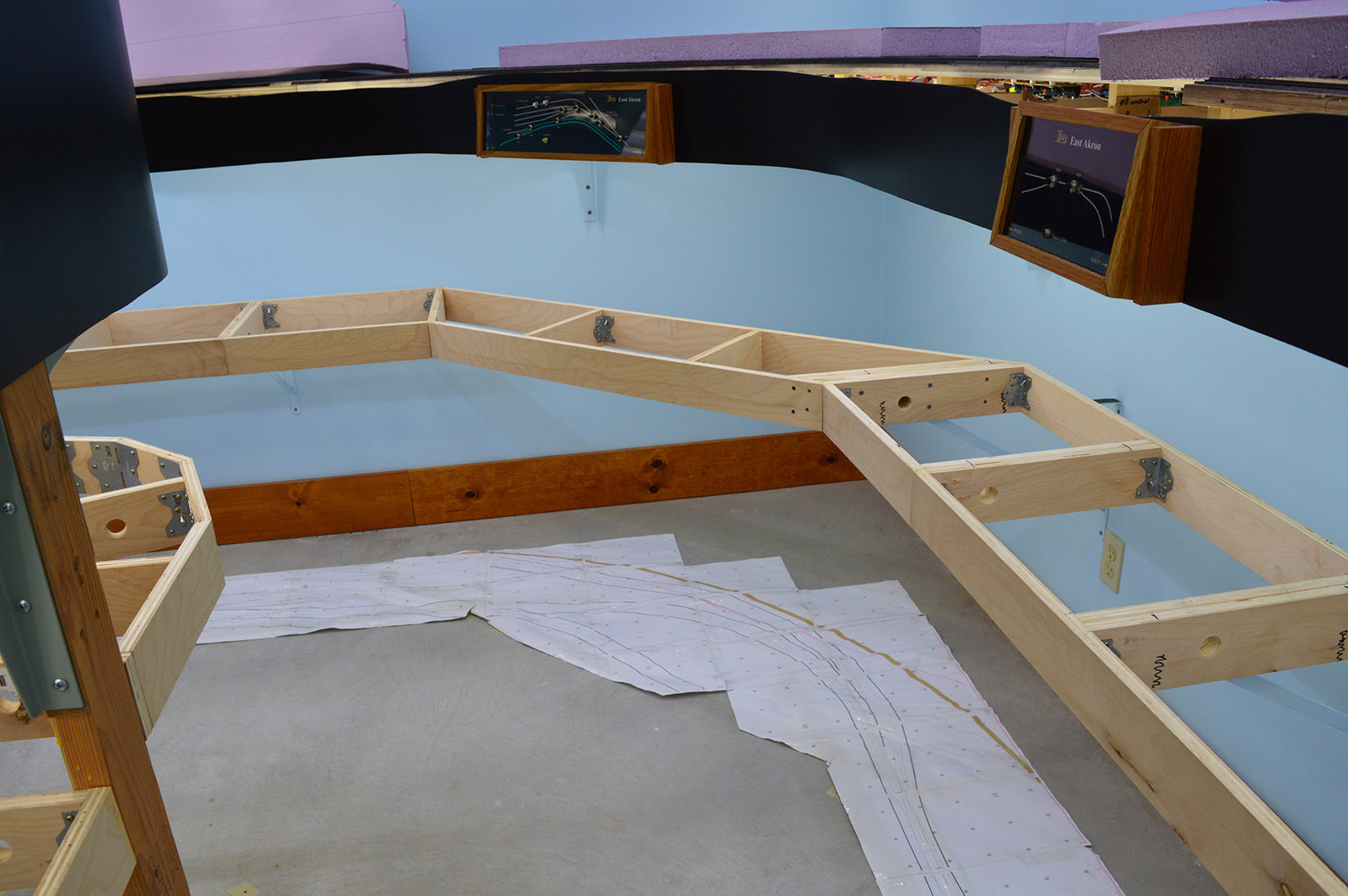
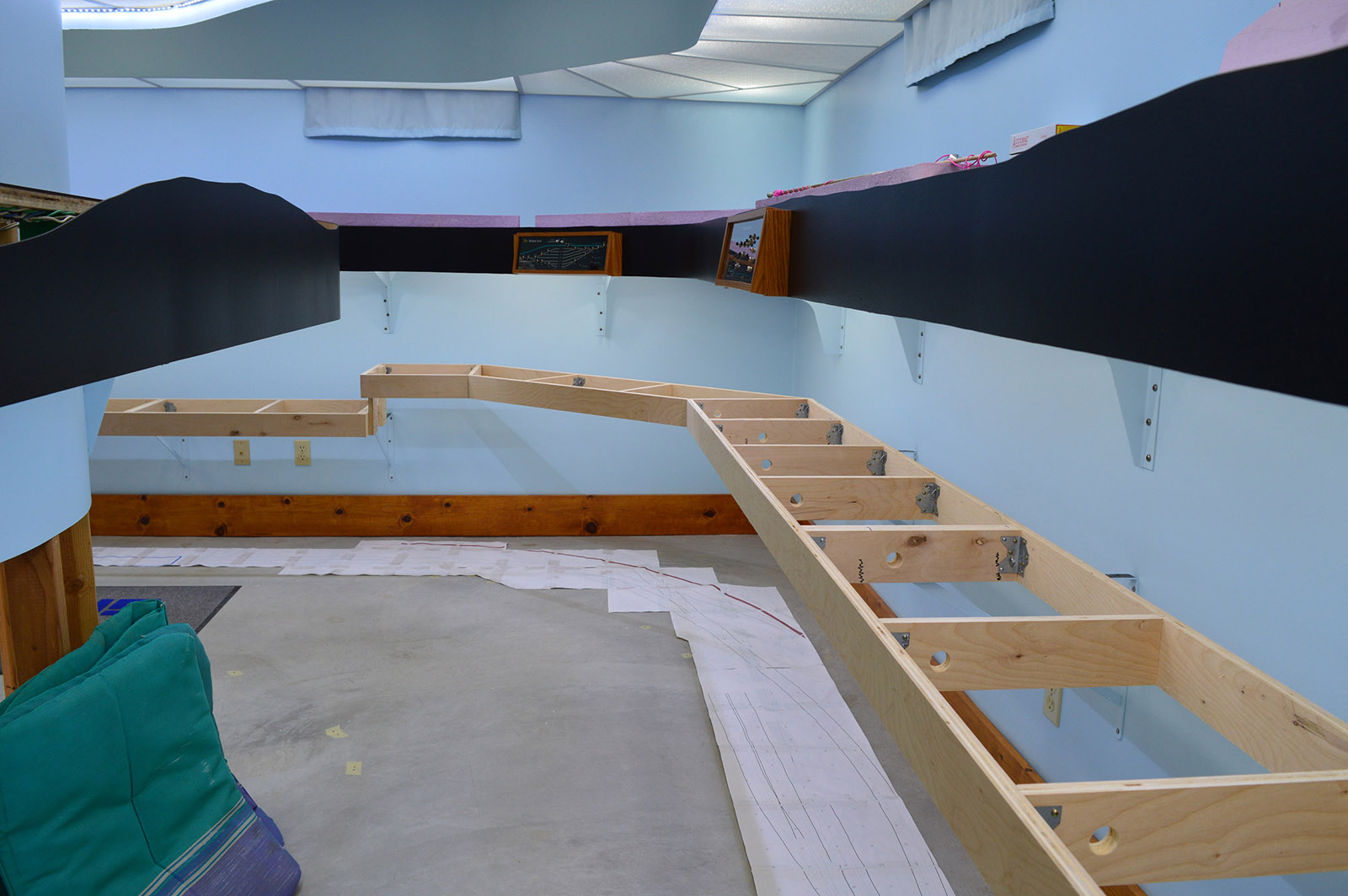
I used my favorite cribbing method, stacked milk crates, to position the benchwork sections at the correct height. Turned out two crates plus a 2×8 on edge sitting on a piece of 1x lumber was exactly the right height. The sections were temporarily clamped together.
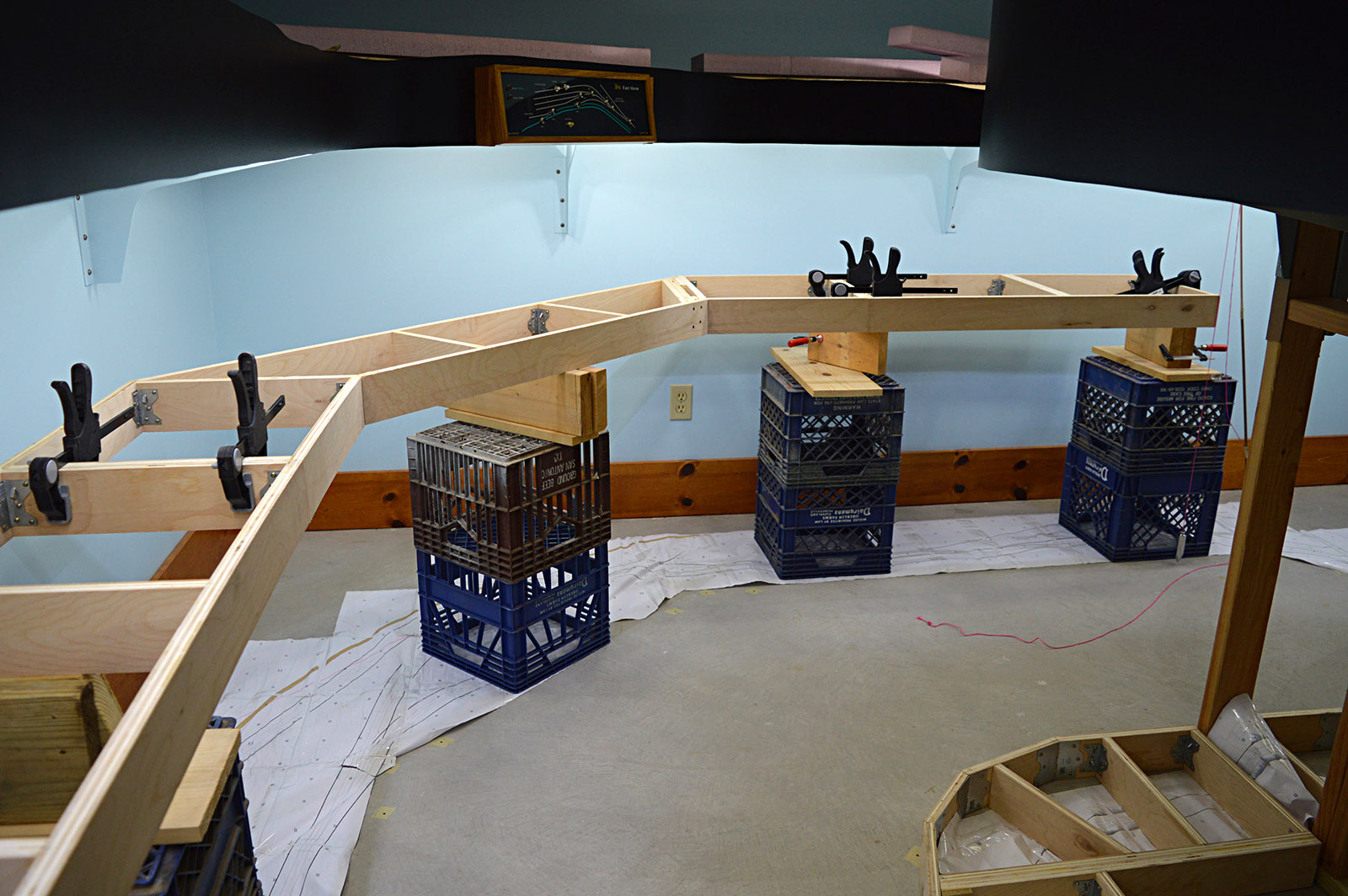
Then came the bumping and nudging to get the benchwork front profile aligned with the upper deck. My plumb-bob-on-a-stick was used to verify the positioning. It took quite some time and patience to get the new benchwork in the right spot all way round. It felt like I must have moved the stick a hundred times by the end of it all.
Wall attachment
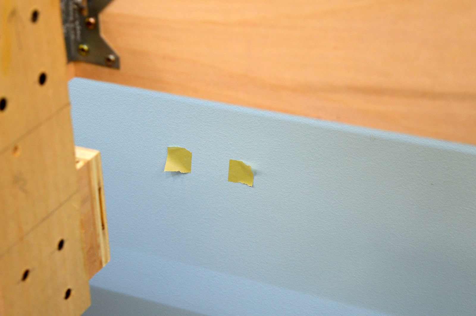
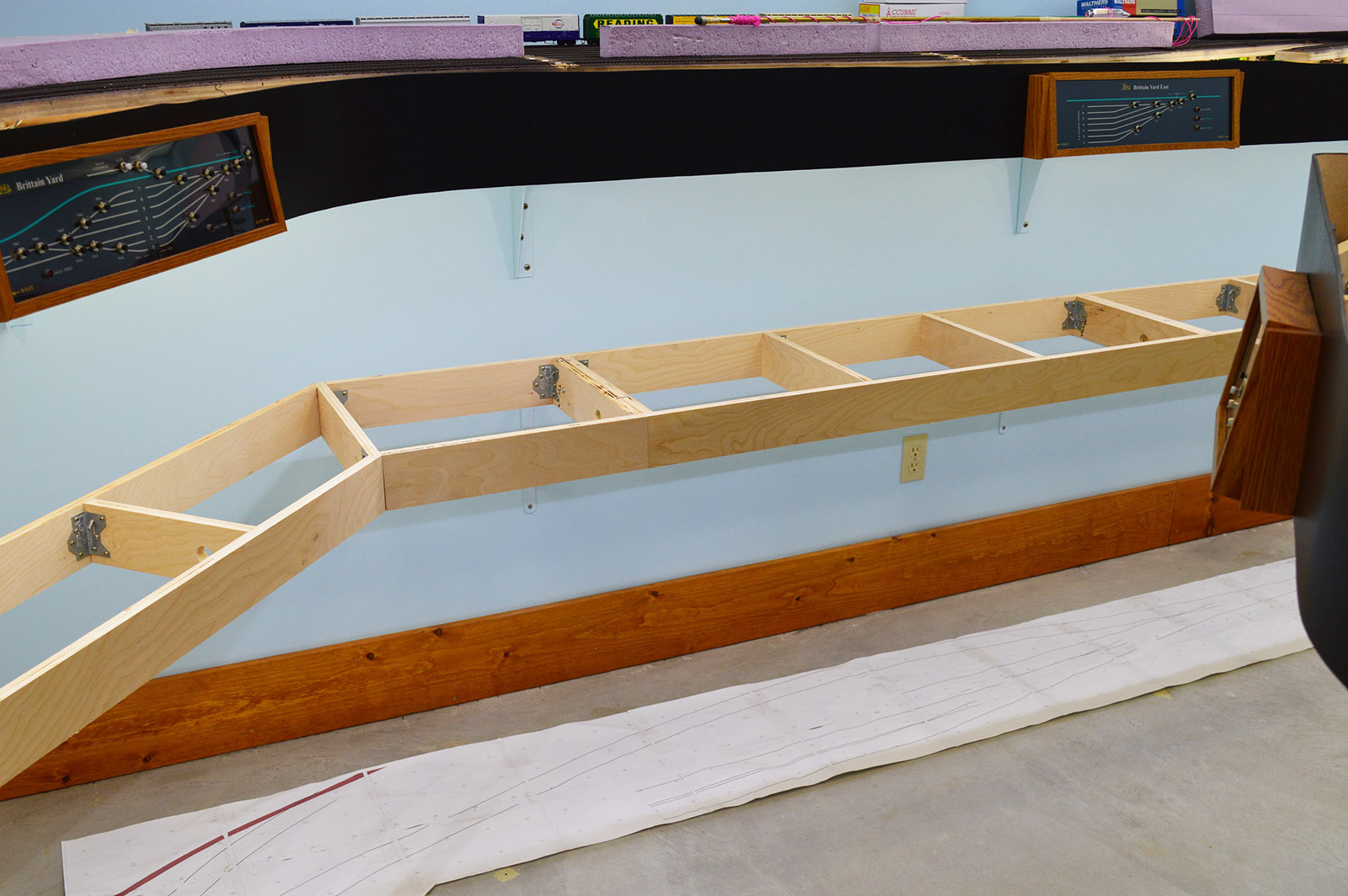
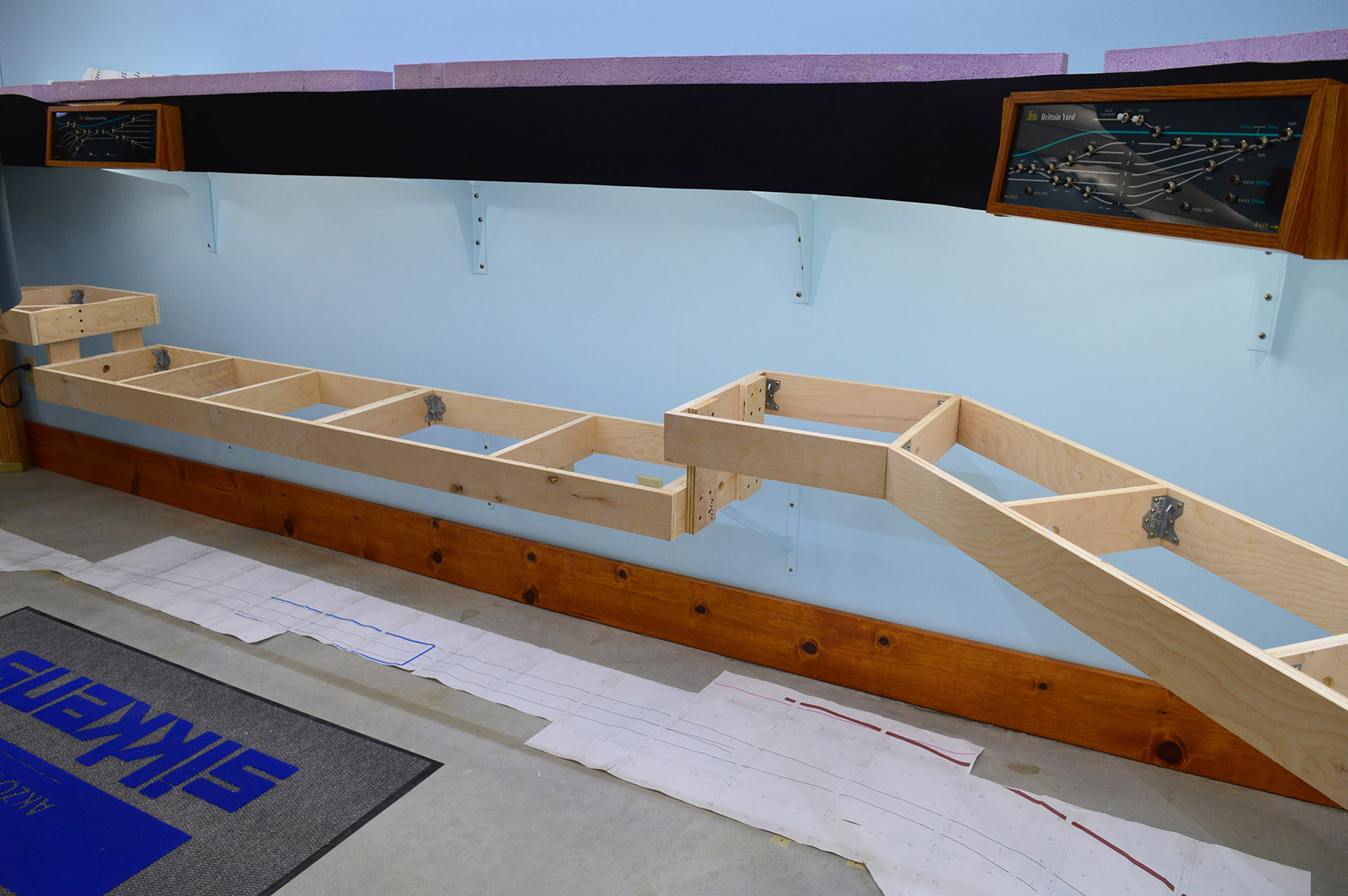
Once I was satisfied everything was in the right place, the clamps holding the sections together were replaced with #14 screws. I then used a stud finder to mark the wall stud locations. Placing tape on the outer edges of the studs kept me from trapping tape behind a bracket.
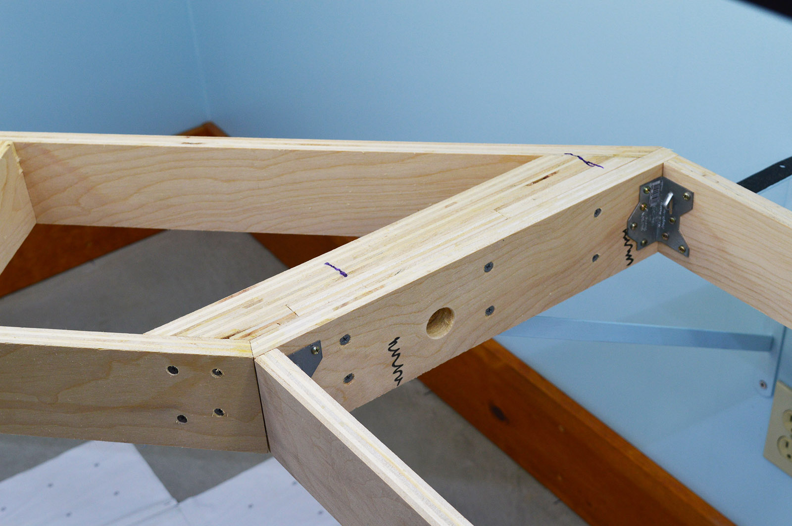
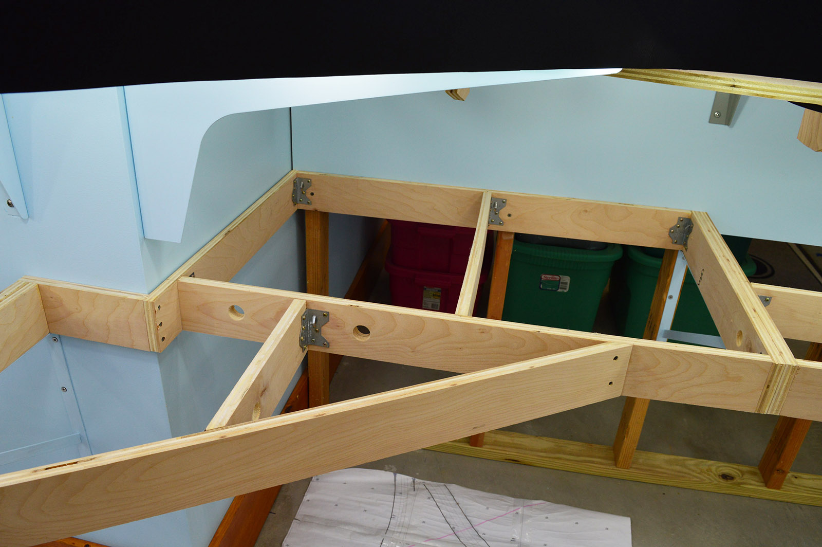
The benchwork was built with doubled up, laminated crossmembers at the bracket mounting points. This gave me a much wider mounting surface to compensate for slight misalignment between wall stud and benchwork crossmember.
Installing the brackets was straightforward. Position the bracket, clamp to crossmember, mark the holes, remove bracket, drill holes, install. #10 x 1-1/2″ screws hold the bracket to the wall, #10 x 2″ screws secure the crossmember to the bracket. Word of advice if you use the Amazon style bracket. The angle brace gets in the way of using a cordless drill, or even a screwdriver for that matter, to drive the mounting screws. Fortunately, a 12″ long #2 Phillips bit solved the access problem
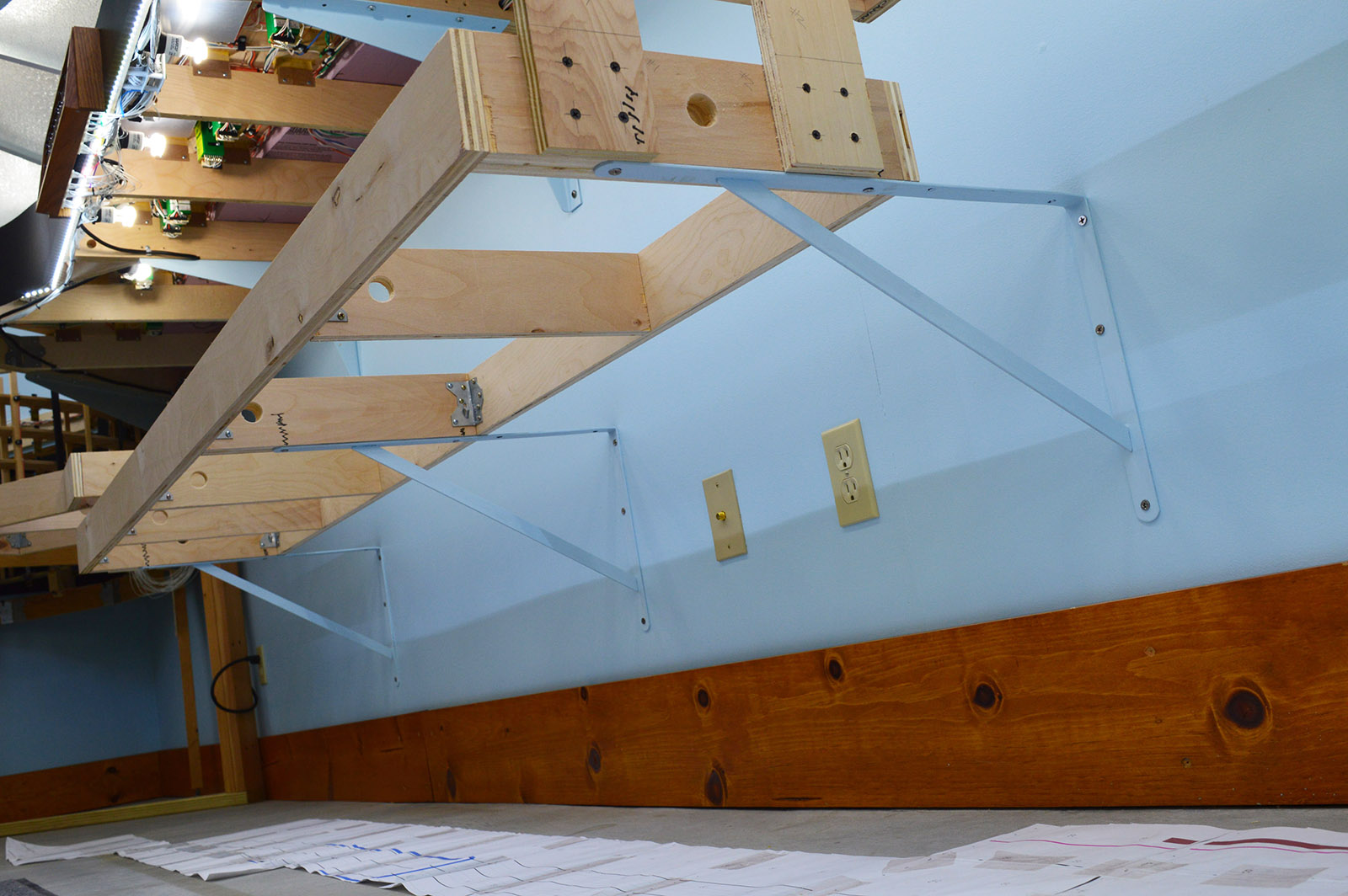
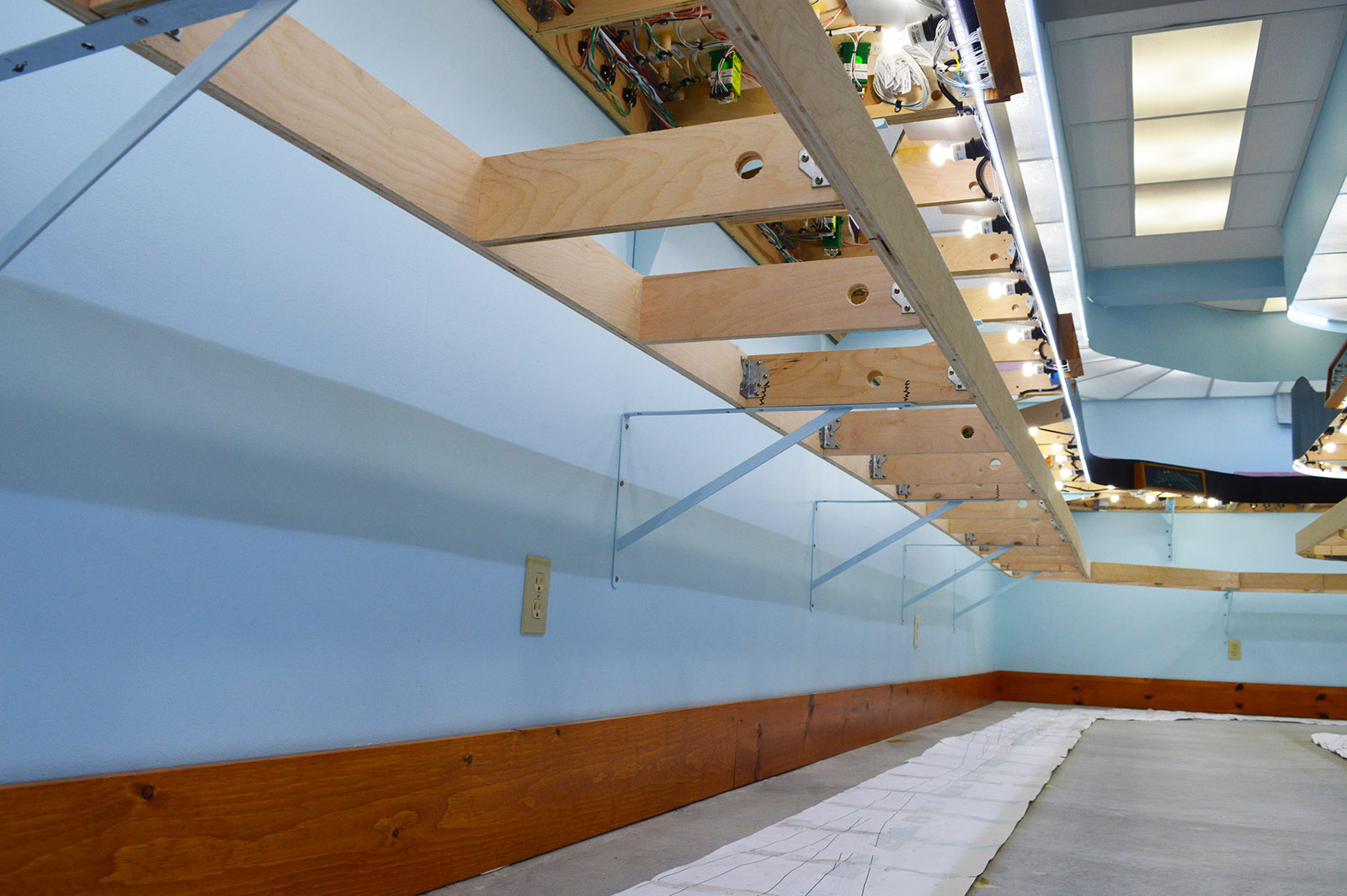
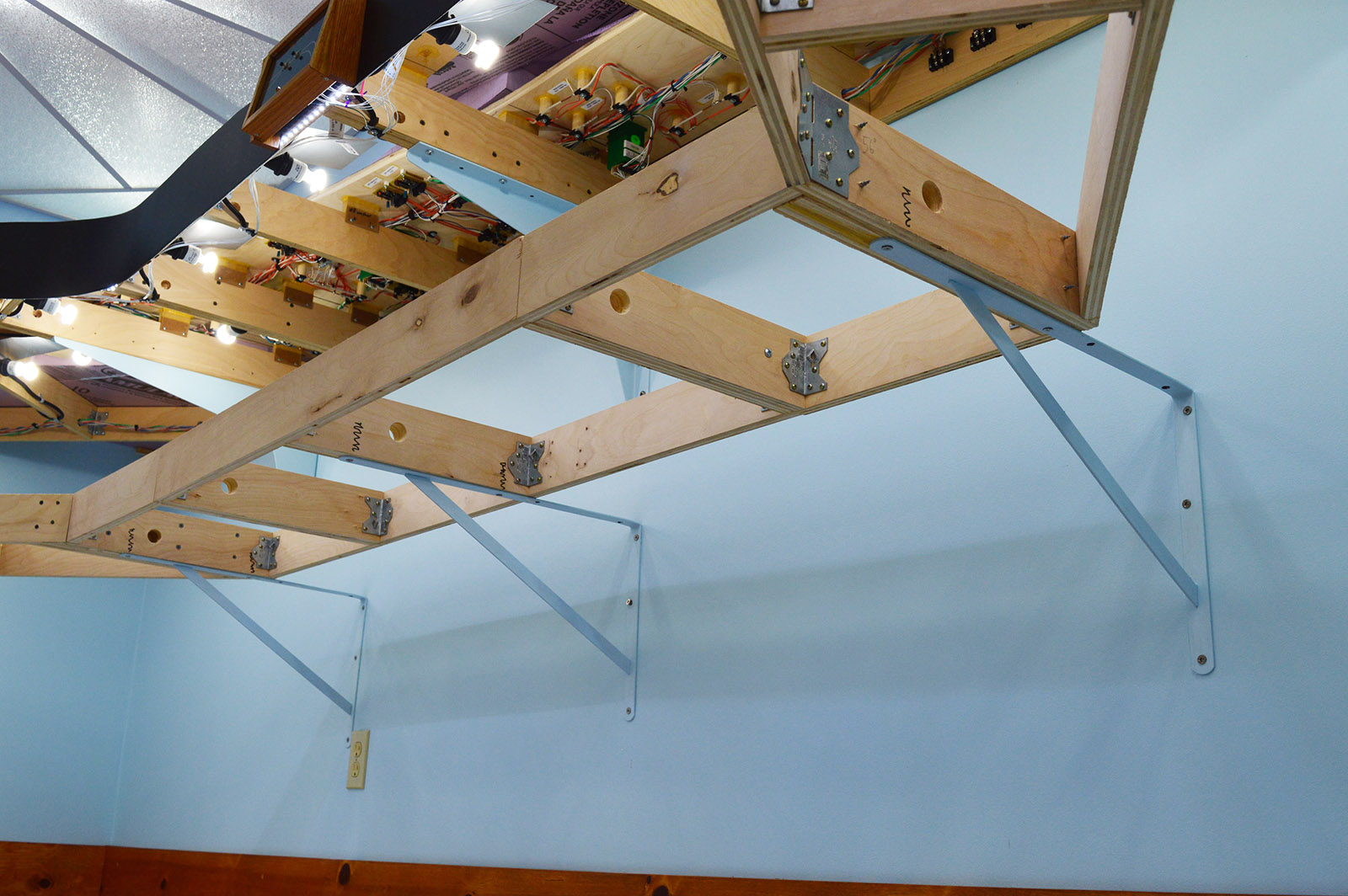
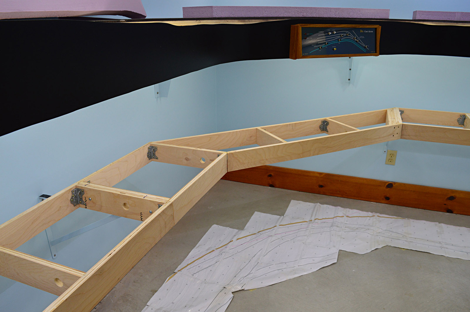
I would have preferred the brackets extend all the way to the front of the benchwork but the available sizes selection did not permit it. Even being shy of the front, the benchwork is still solidly mounted. The fact that the entire thing is one giant screwed together assembly helps tremendously.
Oops!
All the engineering in the world won’t help if the idiot building it doesn’t correctly read his own drawings. Such was the case on one particular section of benchwork. The doubled up crossmember didn’t align with the wall stud on one end of the section. The front edge profile was correct and the overall dimensions were correct but the bracket crossmember was 1-1/2″ off centerline. Referring back to the drawing with tape measure in hand confirmed it. The drawing was correct. I had misread it.
Fortunately the fix was easy. I screwed in a second double crossmember against the original. Problem solved. And it made for one very heavy duty mount. I guess I can consider myself lucky I made the error on only a single section of benchwork. All the others lined up fine.
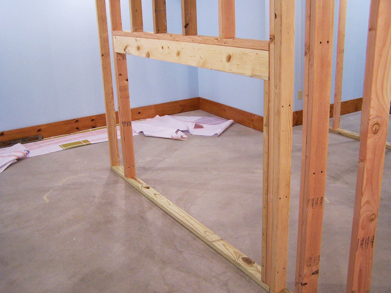
Original north helix location
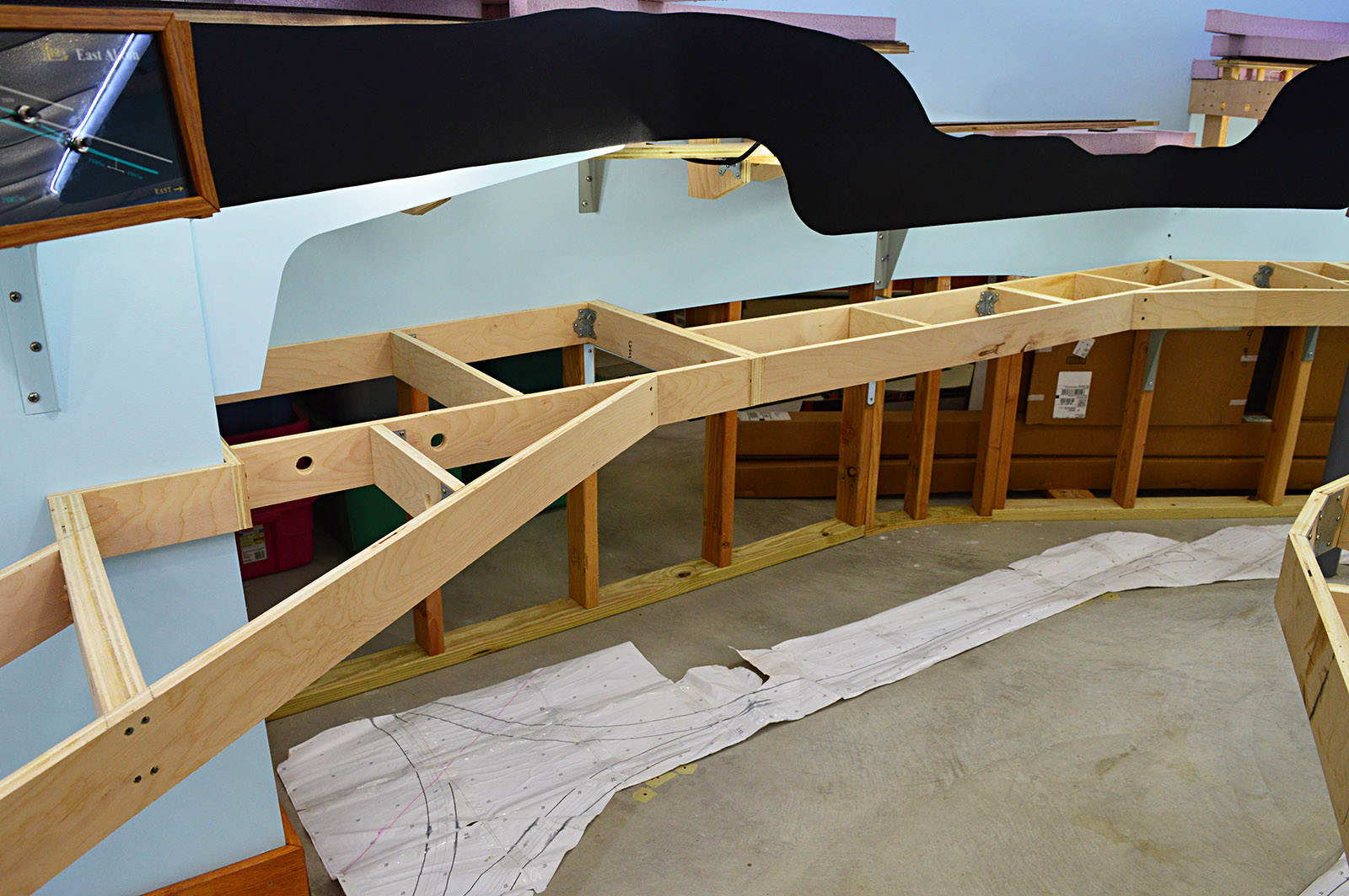
The lower deck redesign eliminated the planned north helix. When originally constructed, a large unobstructed opening was left in the peninsula wall to accommodate the helix. Here is a pic from a long time ago showing the opening.
The benchwork is supported on either side of the opening with big 24″x18″ brackets both on the upper and lower decks. BTW I found a source for lower cost A&M style brackets. Woodworkers Express sells imported generic versions. I bought four of them for the lower deck. They are very similar to and just as sturdy as the original A&M units.
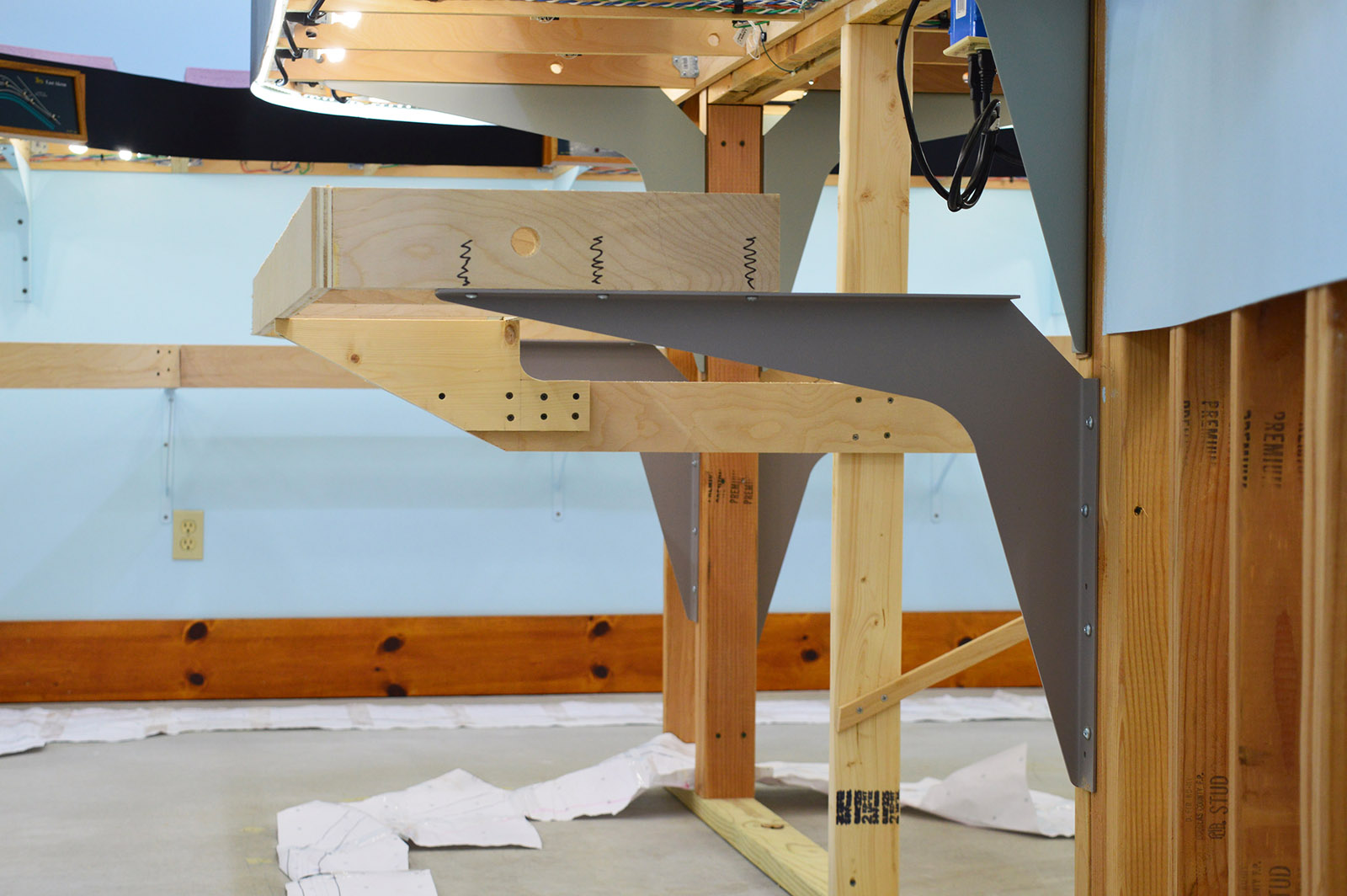
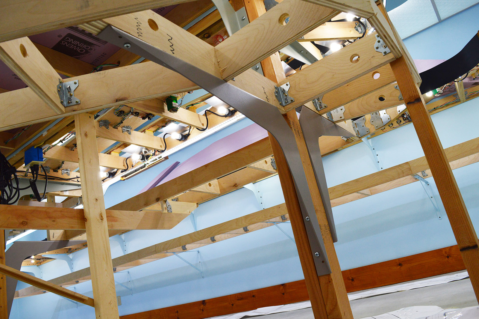
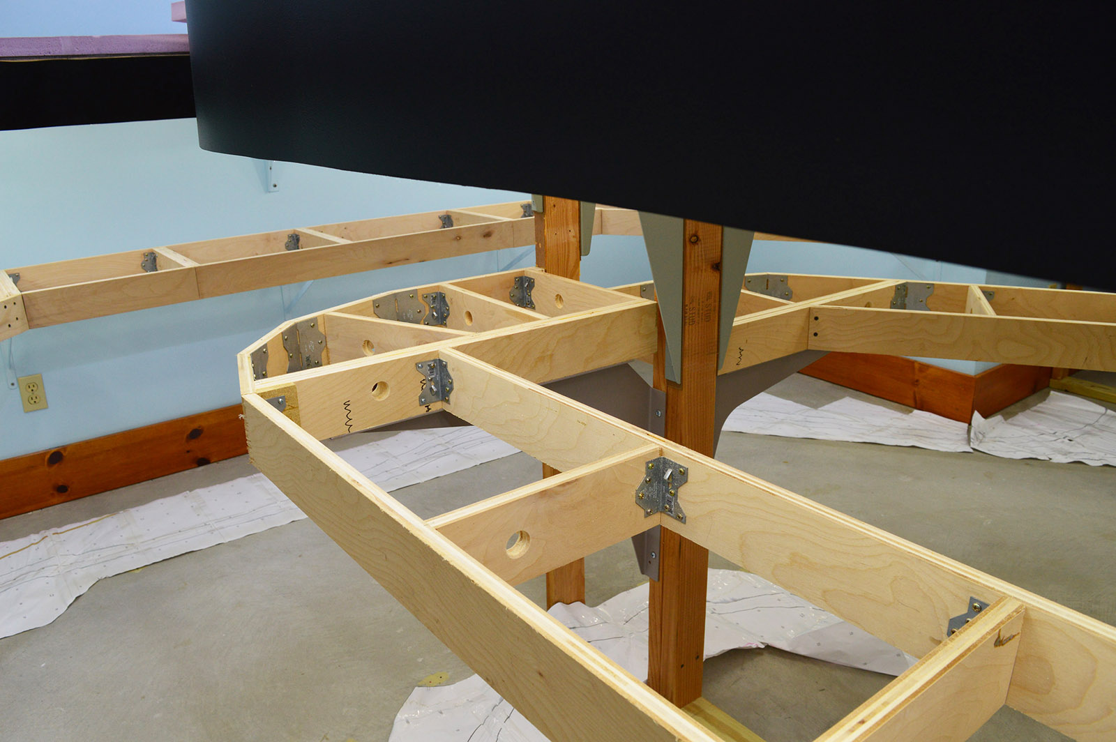
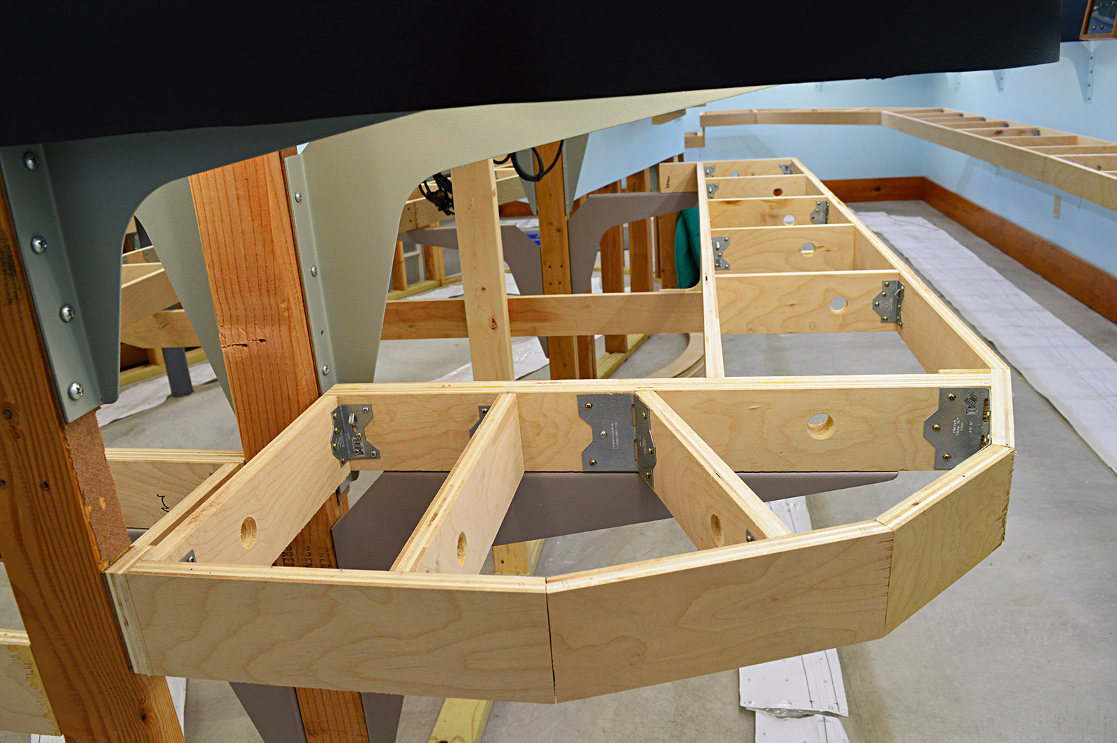
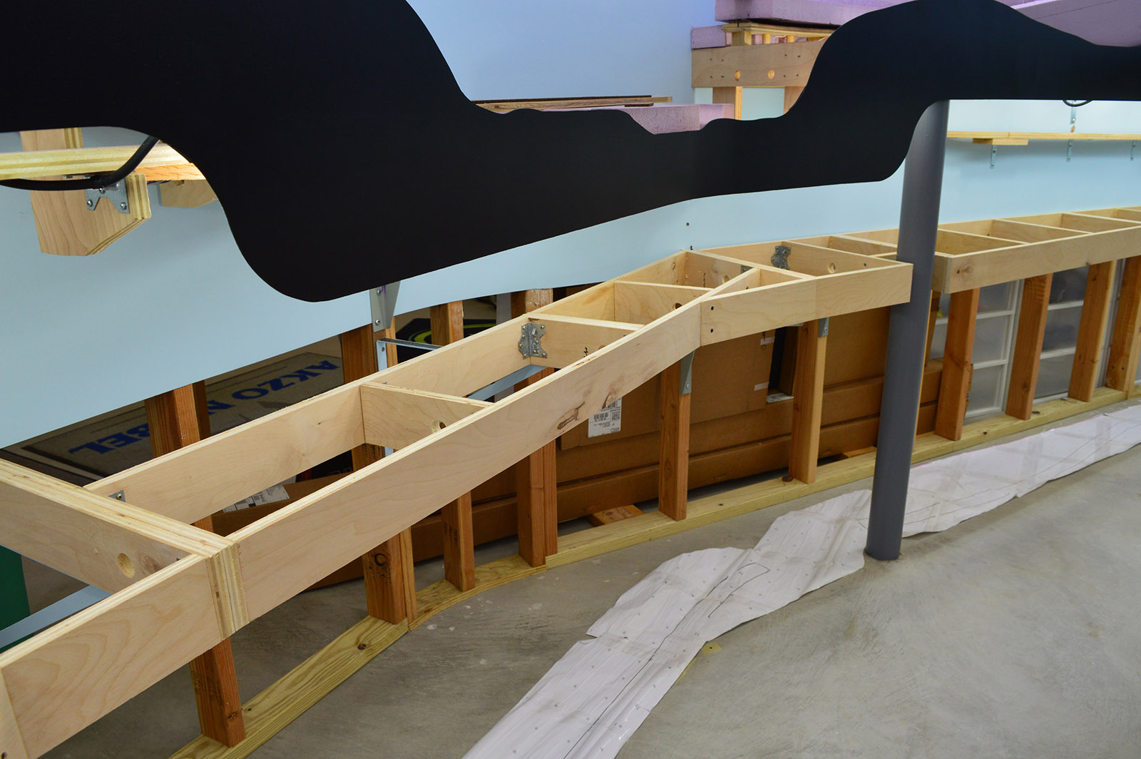
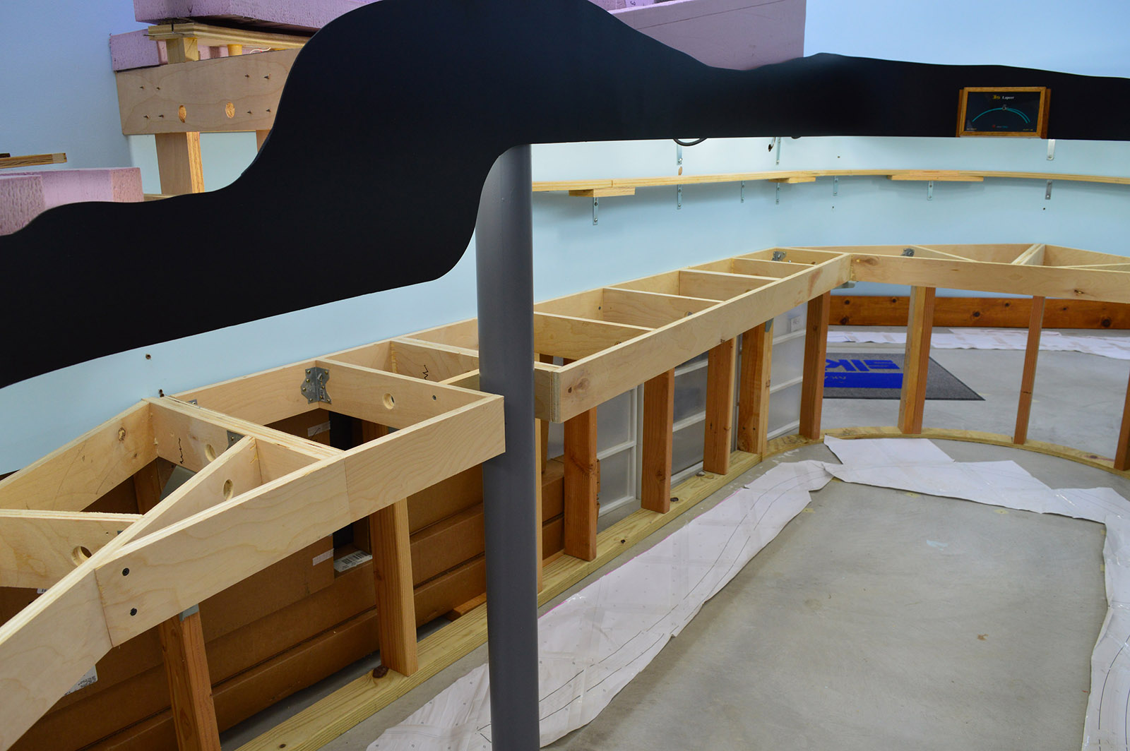
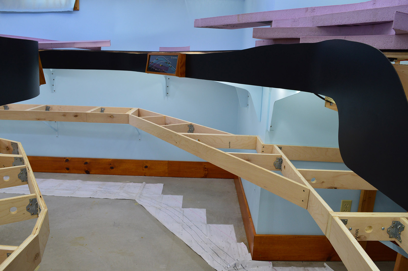
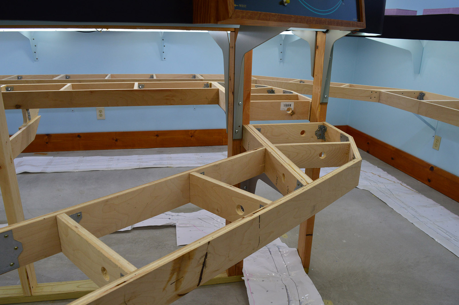
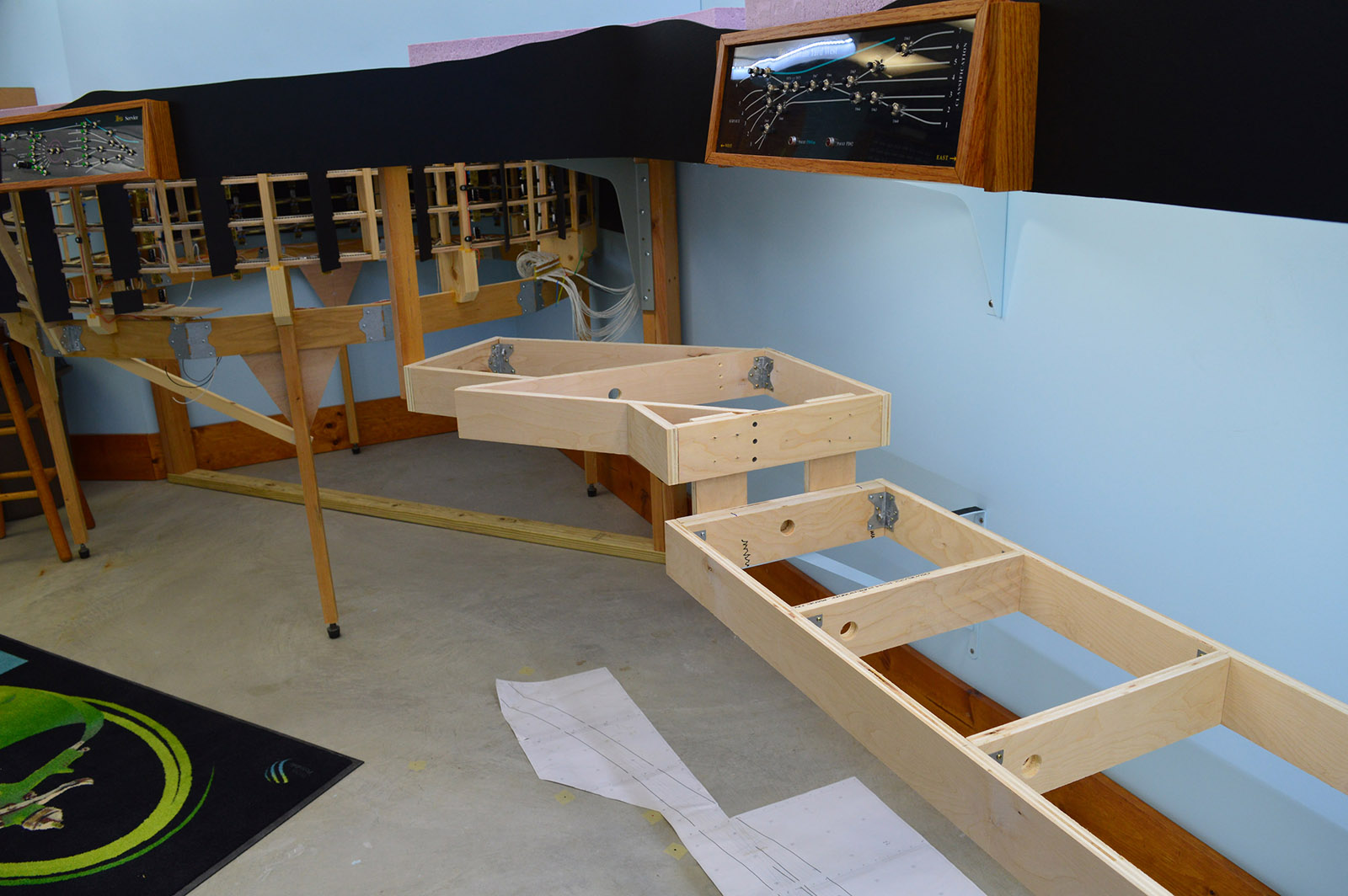
In addition to shelf brackets, the upper deck is fastened all along the peninsula wall adding much support. The lower deck, being much shallower, is not against the peninsula wall so is less well supported for the long span between brackets across the helix opening. To lend support I toenailed (toescrewed?) a 2×4 stud into the middle of the opening and then fashioned a single cross support to brace the benchwork on both sides of the wall.
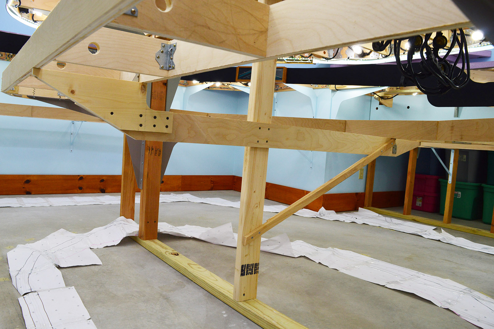
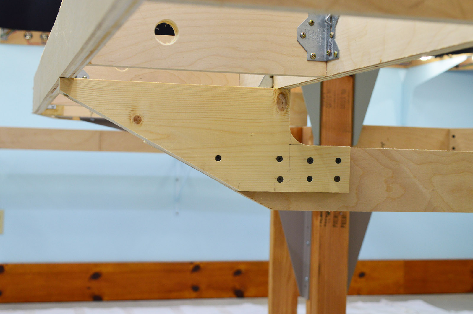
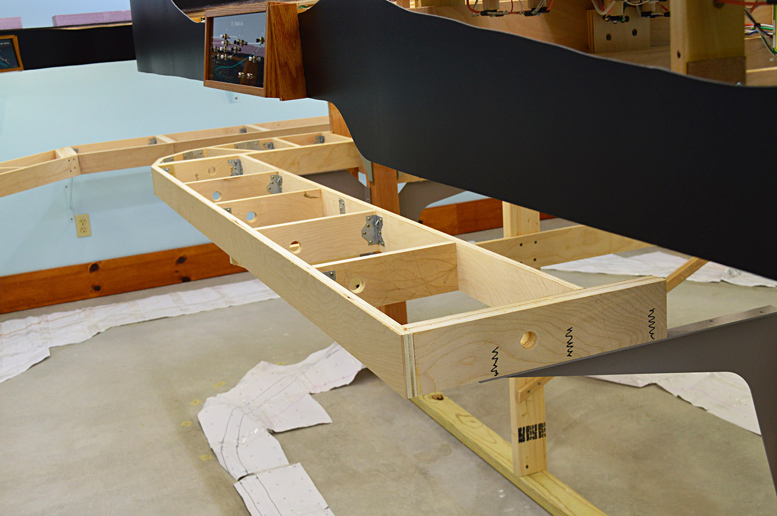
The lower deck benchwork underneath Lapeer is a long way from the wall. Almost four feet. It required a brace to be sufficiently rigid. Because the benchwork is at different heights on opposite sides of the wall, I fashioned a riser plate for the high side.
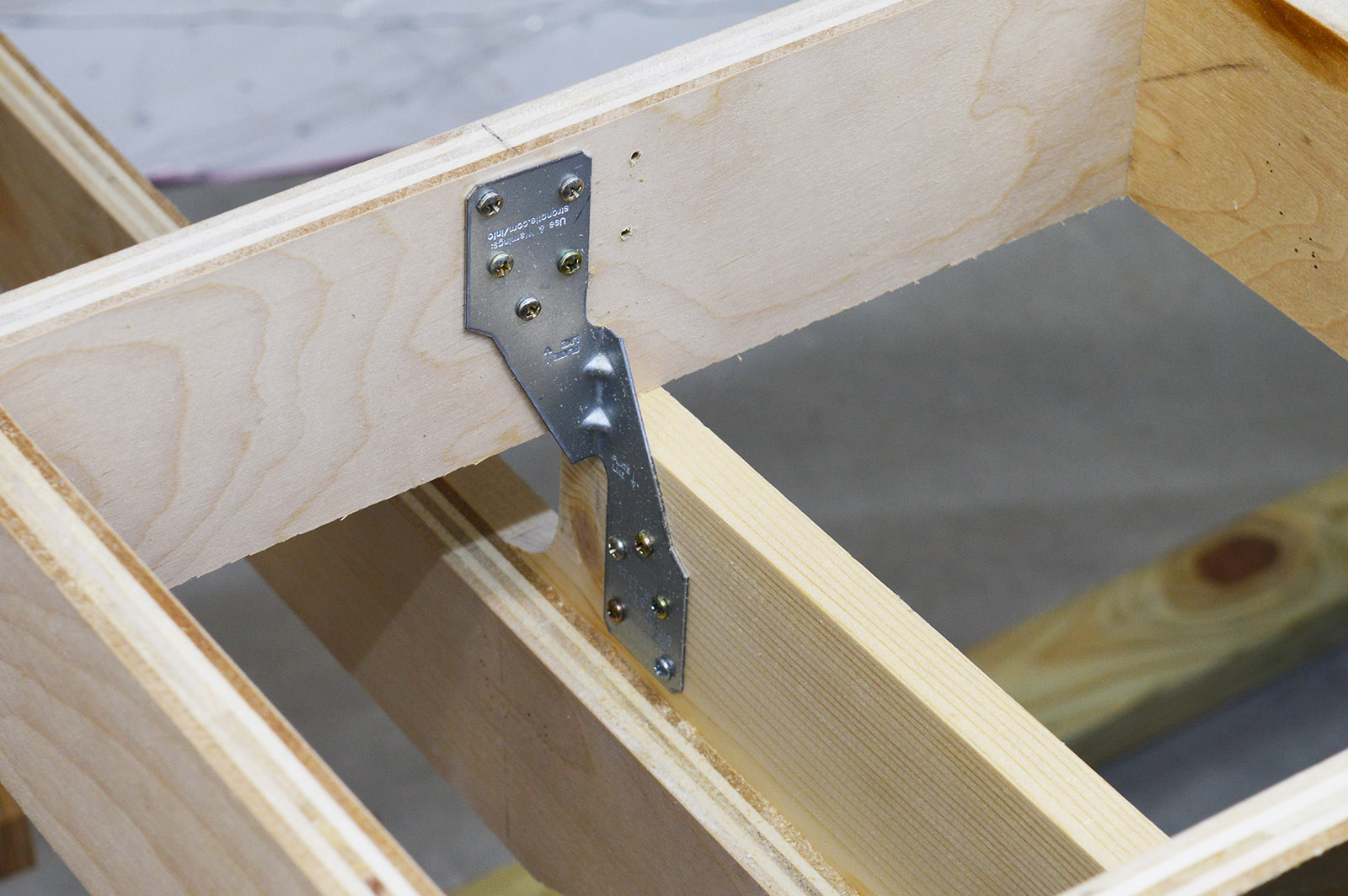
The benchwork is secured to the cross brace with Strong-Tie H2.5A hurricane ties.
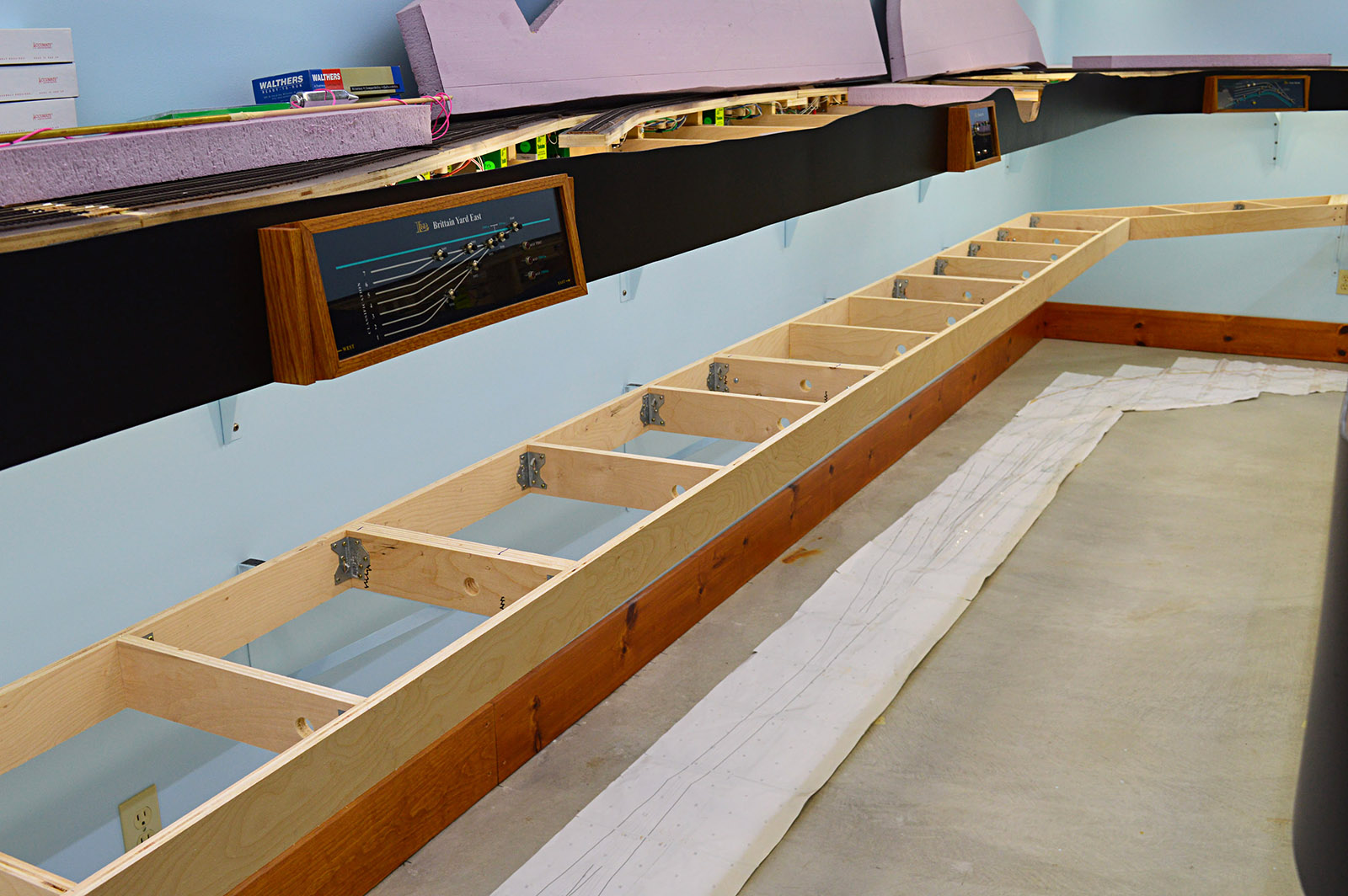
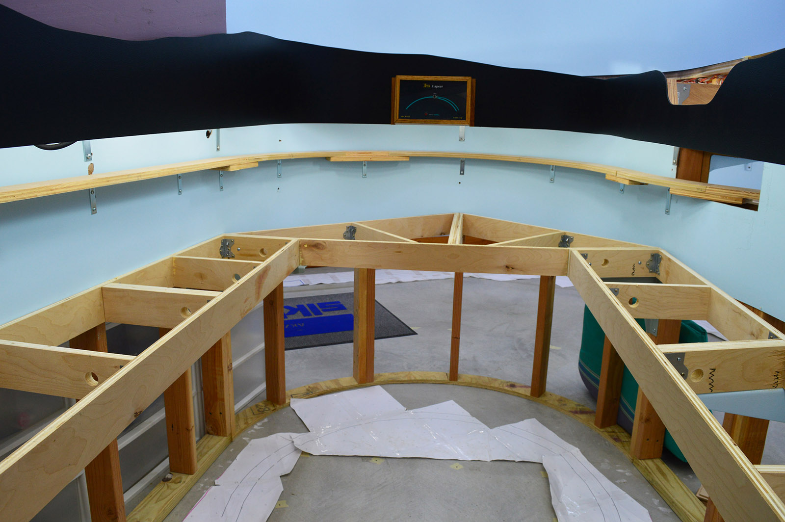
Last detail
Drilling a 1″ hole through every crossmember for wire runs and cleaning up the sawdust mess that I had made was the final step in benchwork mounting. All that remained was to sit down and stare at it for a while.
Next up: backdrops. Stay tuned.
